48
Pannello di comando elettronico com-
prendente: interruttore on/off/resisten-
za elettrica; commutazione automatica
estate/inverno; interruttore velocità
automatica/velocità minima; manopo-
la regolazione comfort ±5°C; contatti
ausiliari (230 Vac) per comando valvo-
la ON/OFF per impianti a 2 tubi, a 2
tubi con resistenza elettrica o a 4 tubi.
Funzione termostato di minima, ciclo di
GHVWUDWL¿FD]LRQH H VHJQDOD]LRQH ¿OWUR
sporco. Montaggio a parete.
3DQQHOOR FRPDQGR HOHWWURQLFR D ¿OR
con display a cristalli liquidi, a 5 tasti,
per la regolazione manuale o automa-
tica di tutte le funzioni dell’apparecchio
in base alla temperatura ambiente
prescelta. Il pannello è predisposto per
LO ¿VVDJJLR D SDUHWH VX VFDWROD GD LQ-
casso a 3 moduli (tipo Bticino 503E).
6FKHGDLQWHUIDFFLDSHUFRPDQGR¿QRD
4 ventilconvettori. Montaggio a bordo
macchina.
KTCVR (fornito separatamente)
KTVD (fornito separatamente)
INT (fornito separatamente)
Electronic control panel including: on/
off/electric resistance switch; automa-
tic summer/winter switchover; auto-
matic speed/minimum speed switch;
comfort ±5°C adjustment knob; au-
xiliary contacts (230 Vac) to control
the ON/OFF valve in 2-pipe systems,
2-pipe systems with electric resistan-
ce or 4-pipe systems. Minimum ther-
PRVWDWIXQFWLRQ GHVWUDWL¿FDWLRQF\FOH
DQGGLUW\¿OWHUVLJQDO:DOOPRXQWHG
(OHFWURQLF FRQWURO SDQHO ÀXVK ZLWK
liquid crystal display, 5 buttons for
manual or automatic adjustment of
all functions of the device according
to the ambient temperature of your
choice. The panel is designed for wall
PRXQWLQJRQÀXVKPRXQWHGER[IRU
modules (Bticino 503E).
Interface card for controlling up to 4
fan coil units. On board installation.
KTCVR (supplied separately)
KTVD (supplied separately)
INT (supplied separately)
Console de commande électronique
comprenant : Un interrupteur on/off/
résistance électrique ; une commutation
automatique été/hiver ; un interrupteur
automatique/vitesse minimum ; une
manette de réglage confort ±5°C ; des
contacts auxiliaires (230 Vca) pour la
commande de la vanne On/Off pour les
installations à 2 tuyaux, à 2 tuyaux avec
résistance électrique ou à 4 tuyaux. Fon-
ction thermostat de minimum, cycle de
GpVWUDWL¿FDWLRQHWVLJQDOLVDWLRQ¿OWUHVDOH
Montage au mur
Ras du panneau de commande électro-
QLTXHDYHFDI¿FKDJHjFULVWDX[OLTXLGHV
5 touches pour le réglage manuel ou au-
tomatique de l’ensemble des fonctions
du dispositif en fonction de la températu-
re ambiante de votre choix. Le panneau
est conçu pour un montage mural sur
boîte d’encastrement pour 3 modules
(Bticino 503E).
Carte d’interface pour commande ju-
squ’à 4 ventilo-convecteurs. Mon-
tage à bord de l’unité.
KTCVR (fourni séparément)
KTVD (fourni séparément)
INT (fourni séparément)
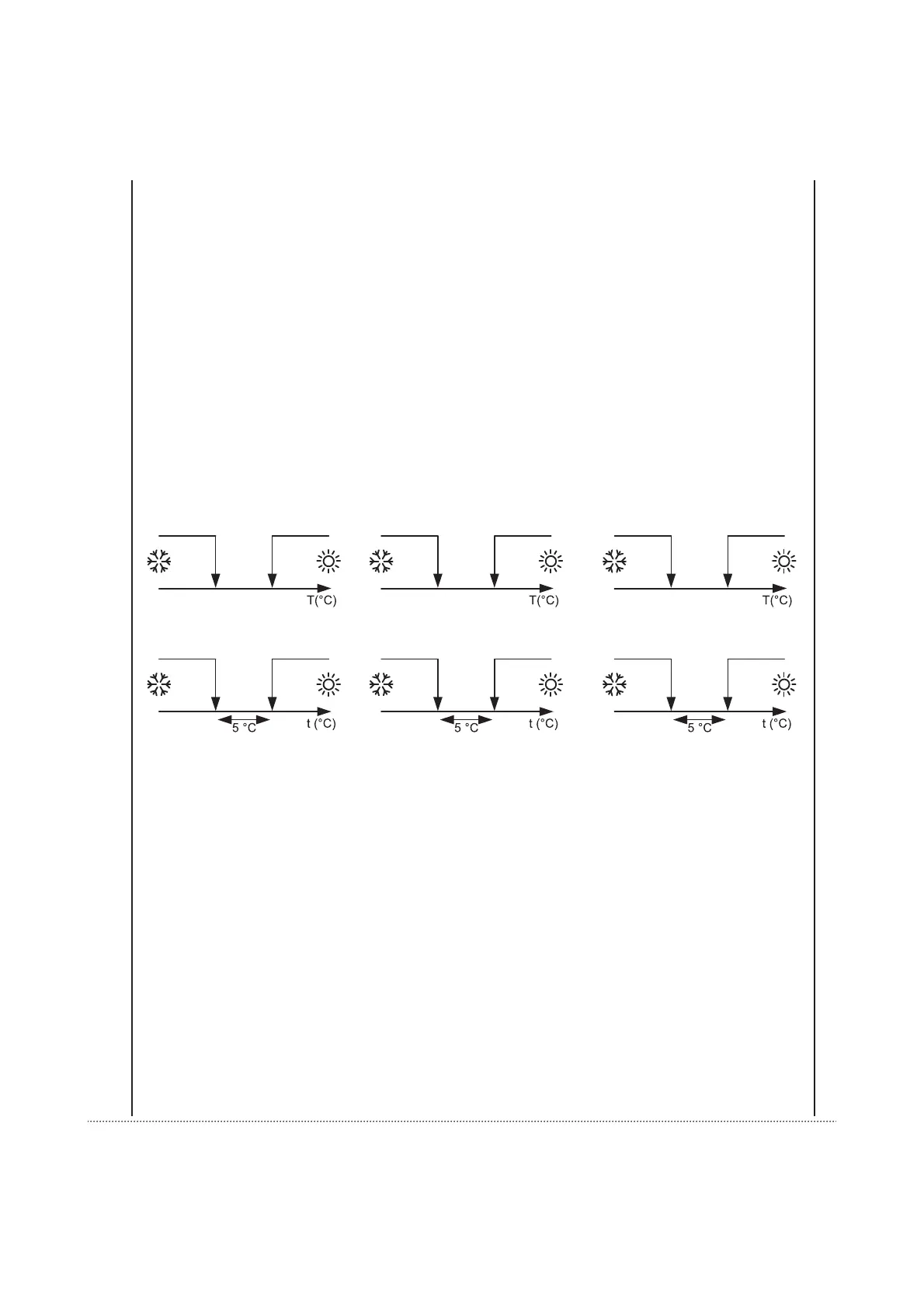
La commutazione tra riscaldamento
e raffreddamento viene fatta auto-
maticamente rilevando la tempera-
tura dell’acqua nel ventilconvettore a
monte della valvola secondo la logica
seguente. La resistenza elettrica, se
presente, può essere attivata.
Impianto a 2 tubi 2-pipe system Installation à 2 tuyaux
Impianto a 4 tubi 4-pipe system Installation à 4 tuyaux
The heating-cooling switchover oc-
curs automatically via detection of
the water temperature in the fan coil
upstream the valve according to the
following logic. If the electric resistan-
ce is present, it can be activated.
La commutation entre chauffage et ra-
fraîchissement est effectuée automa-
tiquement en relevant la température
de l’eau dans le ventilo- convecteur
en amont de la vanne selon la logique
suivante. La résistance électrique, si
montée, peut être activée.
20 32
Stand-by
20 32
Stand-by
20 32
Stand-by
Stand-by
20 25
Stand-by
20 25
Stand-by
20 25