SECTION II: INST ALL ATION AND MAINTEN ANCE
26
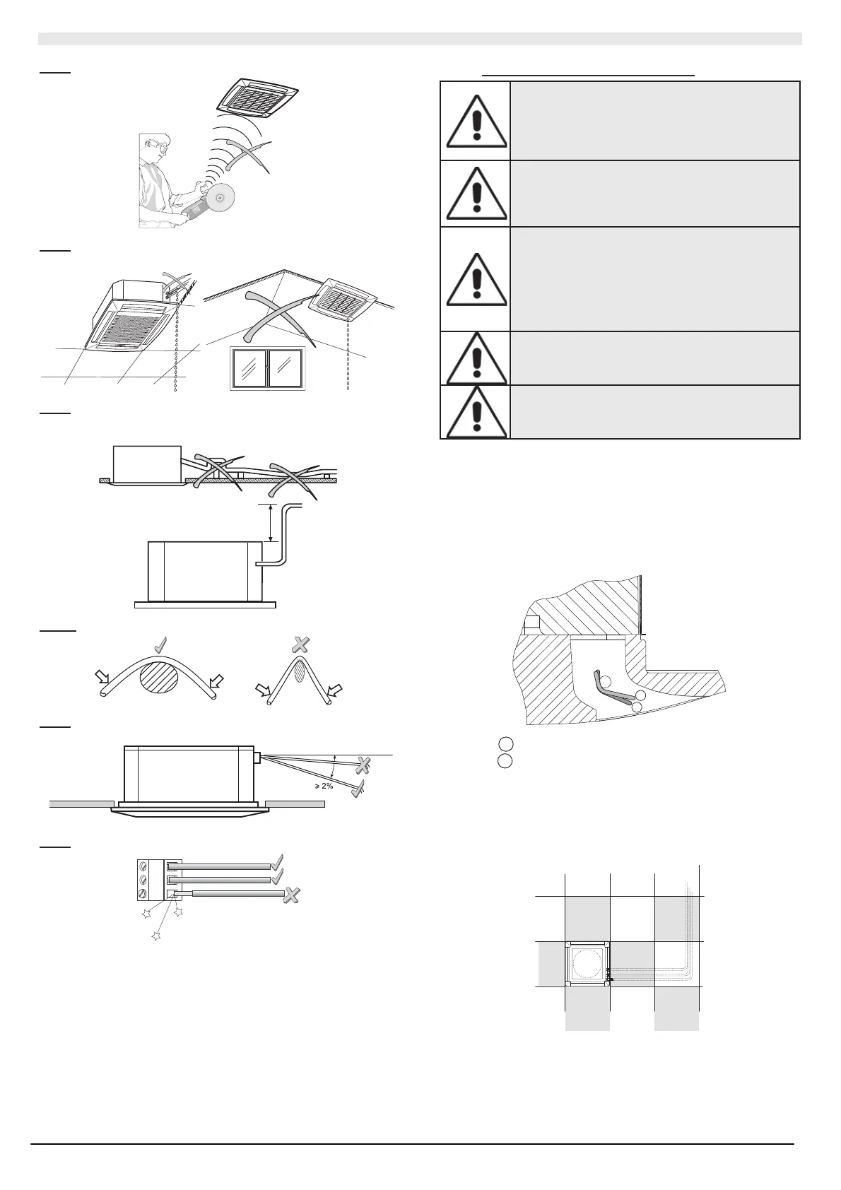
Av oid enviro nments wit h an en hanced pres enc e of high freq uencies .
Av oid
th e p artial insul atio n of the pipes and non-le vel inst allations as
either c an c aus e drip ping .
Av oid
ascending trac ts, away fro m t he u nit, in the condensate drain
pipe. Thes e can onl y be prese nt near by th e unit with a ma xi mum level
differe nce of 20 0 mm wit h respect to t he upper bas e.
MAX. 200 mm
Do not
crush the connec tion pipes a nd th e co ndens ate drain pip e.
Av oid
horizo ntal tracts and ben ds of th e cond ens ate drain pipe; t his
must have a mi nimum sl ope of 2%.
Av oid
loos e elec trical con nec tions .
II.2 INSTALLATION INSTRUCTIONS
DANGER !
Inst all ation must onl y b e c arri ed out b y skil led
technicians, qualified to work on air conditioning
and refriger ation s ystem s. In corre ct inst a llation
could cau se the unit to malfunction, with a
consequent det erioration in performan ce.
DANGER !
The unit must be installed according to national or
local regulation s appli cabl e at the time of
installation. Always u se the personal protective
equipment.
Check that the v oltage and the frequ enc y of the
electric system correspond to those required and
that t he av ailabl e po wer inst alled is suff icient for
other household appliances that are connected on
the sam e e lectri c l ines to f unct ion. Make sur e that
the electrical supply syst em complies with current
National safet y regulations. Make sure that an
eff icient e art h line is av ail able .
The condensate drain pipe of the inner unit must be
extended with a PVC pipe of an intern al Ø 16 mm
(not supplied), long enough for the installation in
question and t herm all y insul at ed.
The unit is not designed to be installed in rooms
used for laundry purposes (IEC EN 60335-2-40).
Follow the indications b elow for the installation procedure:
Install t he unit in a possibl y central position of the ro om. Th e air flo w
direction c an be a djust ed by manuall y moving t he vents acc ording to
the func tioni ng mode (c ooling or heating ). This o ptimis es th e air
distribution in the room.
When f uncti oning in c ooling mode, the o ptimal p osition (2) of th e vents
is that which blows the air towards the ceiling by Coanda effect. In
heating mode, t he vents (1) direct the air t owards t he floor t o pre vent
stratification of hot air in the upper part of the room
1
2
1
Heating : vents i n position to blo w the air.
2
Cooling: vents in position t o blow the air.
For q uick and eas y inst allation and maintenance, the pr e-select ed
position must allow the ceiling panels to be removed and in the case of
masonr y ceilings, the unit can be accessed.
In the case of plasterboard ceilings, the unit housing dimensions must
not e xce ed 66 0 x6 60 mm (mod els 26- 41-5 1) and 9 00x90 0 mm ( models
61-86- 111). In r ooms with hig h h umi dit y, ins ulat e th e f astening brac kets
with s uitable s elf-adhesi ve isolati ng parts.