SECTION II: INST ALL ATION AND MAINTEN ANCE
33
The val ves must onl y open when the fan is functioni ng, i.e. when one of
the cl amps V1, V2 or V3 is energized by LC mains suppl y.
Any el ectric heat er, which mus t onl y be of the type installed in the
factor y, must onl y be powered when a fan is func tioni ng.
3 2
4
1
Y4 Y2
YX LL N N PE
TB
A
O
B
G
1CM
1CF
1
3
5
PS
C
1
3
5
1LIV2LIV
G O BA
C
FS FS
M
R
C
B
WW
A
A B
B
Y/G
Y/G
FILTER
L
N
PE
Y/G
12345
PENL
A+
A-
X2M2
X3
M1
RS232
230V-1ph-50Hz
L N
IG
UTNC-I
HEAT COOL
ON/OFF
0-10Vcc
HEATING INPUT SIGNAL (230Vac)
COOLING INPUT SIGNAL (230Vac)
II.2.5.9 Anti-freezing protection
IMPORTANT !
When the unit is out of service, dr ain all the water
from the circu it.
IMPORTANT !
Mixing the wat er with glycol modifies the
performance of the unit. Pay attention to the safet y
instructions on the p ackage regard ing glycol.
If the unit is not used during the winter period, the water c ontained in
the system may fr eeze. To prevent this, all the water contained in the
circuit must be emptied before the onset of winter. However, if the
operation of draining the system seems too laborious, a suitable
quantity of anti-freez e liquid can be mi xed with the wat er instead.
If the system needs to be empti ed, remember that a water head always
remains into the coil and it may freez e in c ase temperature goes bel ow
0° thus causing the heat exchanger failur e. The heat exchanger can be
totall y emptied by openi ng the val ves and bl owi ng in air in eac h val ve
for 90 sec onds at a mini mum press ure of 6 bar.
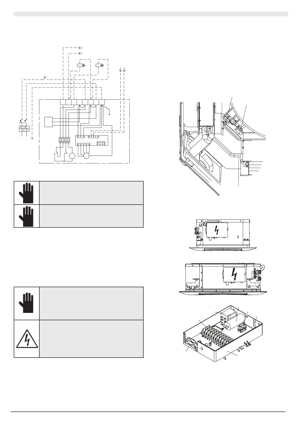
II.2.6 ELECTRICAL CONNECTIONS
IMPORTANT !
The electrical connection of the unit mu st be
carried out b y qualified p ersonnel, in complian ce
with the regulation s applicable in the country wh ere
the unit is in stalled. RHOSS S.p.A. shal l not be held
liable for damag e to persons or prop ert y caused b y
a non-compliant electrical connection.
DANGER !
Always install a general automatic swit ch in a
protected ar ea n ear the machine, which h as a
characteristic d elayed curve, sufficient capacit y and
breaking po wer. There must be a min imum dist ance
of 3 mm bet ween the contacts.
An earth connection is compulsor y by law to
ensure u ser saf et y while the machin e is in u se.
Chec k that the voltage and the frequenc y of t he electrical s ystem
correspond to 230V (±10%) single phas e at 50 Hz (±7% in case of units
with electric resi stanc e); that the available installed power is sufficient
for running the equipment and that the suppl y cables are of adequate
section for the maximum c urrent r equired.
Make sure that t he electrical s upply system complies with c urrent
national safety regulati ons.
The connections must be impl emented in accordance wit h the diagrams
supplied with the machi ne. Use a H05VV-F-type, flexibl e, double-
insulated, bipolar + earth cable wit h a 1.5 mm² section to connec t the
unit to the mai ns (2,5 mm² in case of elec trical heater).
IMPORTANT: the unit with the elec tric heater is equipped with two
thermost ats; one with automatic rearm and one with manual rearm that
can be reacti vat ed. Il riscaldatore elettrico è installato esclusi vamente in
fabbrica. E’ assolutamente vi etato l’us o suppl ementare di altri
riscaldatori montati i n loco. L’inosser vanza di ques ta norma c ausa il
danneggiamento dell’unità e c omporta l’immedi ato annullamento della
garanzia. The electric heater is fac tor y installed. The us e of other
electric heaters is absolutely prohibited. F ailure to follow this safety
requirement causes unit damage and voids the warranty.
A
B
A Thermostat wit h manual reset
B Thermostat with automatic res et
1
1
1
2
3
4
5
6
7
UTNC-EV
1 Electrical box
2 Cable holder
3 Terminal block
4 Electric heater rel a