SECTION II: INST ALL ATION AND MAINTEN ANCE
32
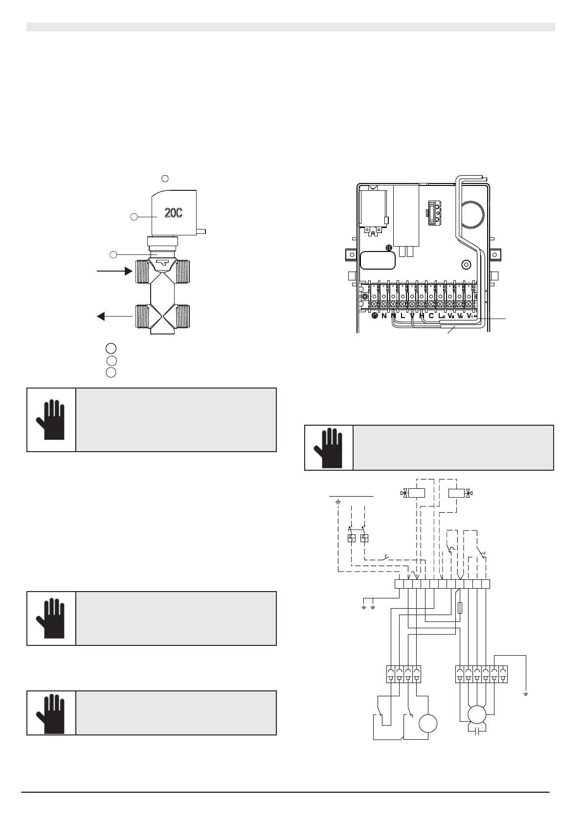
II.2.5.7 Functioning of the motorised electrothermal
valve
This 2- 3- way valve is of the OPEN/CLOSE type with ver y slow travel.
It is not a modulating val ve so it has no PTC.This val ve is driven, as a
sensible element, by t he ambient t her most at of t he “c assett e” u nit.
The 2- wa y val ve is nor mall y clos ed t o t he coil with no po wer ed actu ator
side. The 3-way val ve is nor mall y clos ed to the coil with no powered
actuator sid e while is op en to the bypass way side . Whe n t he ro om
tempera ture do es n ot s atisf y t he th ermos tat , the valve opens after
about 3 minut es about to allow wat er to circul ate i n t he c oil.
If the ro om temperatur e satisfi es t he ther most at or if t he electric power
has been s witched off , t he valve is clos ed aft er a bou t 3 minut es to wards
the c oil an d is opene d t o wards the b ypass.
1
2
A
A
Val ve
1
Electrot hermal h ead
2
Val ve bod y
In an em ergen cy, the valve can be opened manually
by loosen ing the nut and removing the electric
actuat or. On ce t he eme rgenc y i s re solved,
rememb er to re st ore t he automatic function of the
valve b y re-positioning the electric actuator. Failure
to do so can cau se condensation due to the
pass age of water, ev en if not po wer ed.
II.2.5.8 Instructions to be followed if valves
supplied by the installer are used
W ater connections
Use flat-e nd val ves with a 40 mm int era xis f or sizes 26-41-51 and a 74
mm inter axis for sizes 61- 86-111.
Install t he val ves following the manuf actur er instructio ns; refer t o t he
relative figures f or th e c onnectio ns t o t he unit.
Carefull y insul ate the pi pes, th e val ve units a nd th e coil fitti ngs (cold
wat er side) s o as to prevent th e co nd ens ation th at c an form on them
from dripping on to the false ceiling.
When the system is filled with water, verify the tightness of all the
fittings.
RHOSS S.p.A. cannot guarantee tightness
efficiency of the valve units supplied b y the installer
as the se are not fa ct or y-tested. Th eref ore , the
Company shall not be h eld li able for an y
malfunctioning valve unit and damage cau sed by
dripping.
Electrical connections
Conn ect t he ro om control f ollo wing th e instruc tions r elati ve to the
control used.
ATTENTION!
Route the cables through the electrical box as
shown in fig.
Conn ect t he val ves accordi ng to t he follo wing instruc tions, using t he
relative wiring diagrams.
The t ype of valves used must cl ose t he water i nlet t o t he unit in t he
even t of a power c ut.
2-position (ON-OFF) 230V v alv es f or UTNC-EV
In this case the chilled water valve must be piloted by the 230V ON-
OFF sig nal from clamp V , and the hot water val ve from clamp H.
2-position (ON-OFF) v alv es with a v oltage other than 2 30V f or
UTNC-EV
If a ro om co ntrol listed in the acc essories t abl e is us ed, follo w t he
instructions in the previous paragraph, installing two 230V relays to
clamps V-N and H-N that will control the valve opening.
1
2
UTNC-EV
1 Hot valve or hot valve relay
2 Cold valve or cold valve relay
Control connection for UTNC-EV
If a l ow- volt ag e co ntrol is use d or t he room co ntrol ins talle d is not
include d in th e acc essories tabl e, t he c onnecti ons mus t be imple mented
on t he termi nal boar d of th e unit.
ATTENTION!
Failure to comply with these connections can cause
the condensation water to overflow from the tray.
N
L
IG
32
4
1
21 6543
NPE VNL HCLC V2 V1V3
1
2
F
F=1A type F
A
Y/GY/G
TB
A
C
W
R
Y/G
A
B
O
B
G
1CM
1CF
3CM
3CF
1
3
5
PS
C
1
3
5
1LIV2LIV
GO BA
C
FS FS
M
C
W
R
B
Y/G
CV
ON-OFF
MAX
MED
MIN
HEATCOOL
COLD
HOT
230V-1ph-50Hz
UTNC-EV
HOT Hot
COLD Cold