SECTION II: INST ALL ATION AND MAINTEN ANCE
27
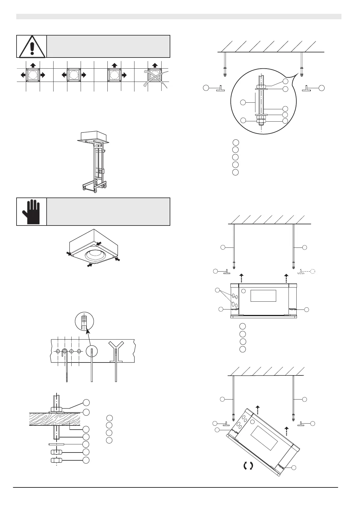
Use th e relati ve KIT (KC B) to cl ose on e or t wo air flo w ven ts.
ATTENTION!
Do not close the air flo w in an y wa y other than that
shown in the diagram. A maximum of 2 vents can
be clo sed.
II.2.1 PRE-INSTALLATION
Transport th e pac kag ed unit as close as possible to the inst allation
location. For f urth er prot ection, t he con trol and the grid are su pplie d in
separa te pac kaging. The unit i nstalla tion is facilitated when a fork lift is
used .
IMPORTANT !
Do not handle the unit from the conden sate drain
pipe or the water connections. Hold it from the four
corners .
II.2.2 INSTALLATION
Mark t he positio n of e ach su pport , the c onnectio n pi pes and
cond ens ate drain pipe and the el ectric suppl y a nd c ontr ol cabl es (see
dimensions). The sup plied cardbo ard t emplat e can b e us ef ul for t his
purpos e. T he tie-rods c an be installe d as indic ated in th e fig ure,
depending on the type of ceiling.
An e xa mple of fast ening t o a woode n struct ure:
1
2
3
4
1
1
4
1
Bolt
2
Wooden structure
3
Thread ed tie-rod
4
Washer
Once the four tie-rods are i nstalled, screw i n the bolts without tightening
and insert the washers as i ndicated in t he fig ure:
1
3
4
1
1
4
2
5
5
1
Bolt
2
Gap for f astening brac ket
3
Thread ed tie-rod
4
Washer
5
T-profile
First position the connectio n pi pes as d escribe d in t he "Water
Conn ections" par agraph an d re move a T-pro file f or a q uic ker and
simpler installation.
Carefull y lift t he unit ( with out th e fra me), grabbing it fr om th e four
fastening brac kets (or t he four corners) and insert it int o the f alse
ceiling.
5
5
3
3
6
6
7
3
Thread ed tie-rod
5
T-profile
6
Fasteni ng brac ke t
7
Wat er con nec tions
If a T-profile cannot be re moved , t he unit mus t be tilted (this c an onl y be
carried out if the false ceiling is higher than 300 mm).
5
5
3
3
6
6