SECTION II: INST ALL ATION AND MAINTEN ANCE
30
II.2.5 WATER CONNECTIONS
IMPORTANT !
It is ver y important for the water conn ections to be
implemented wit h gre at ca re b y sp eci ali sed
personnel.
II.2.5.1 Connection to the System
Use thre aded gas kets a nd suit able material f or th e water co nnections to
the he at e xchanger or t he val ves i n order to guaran tee a perf ect s eal.
The unit is eq uipp ed wit h female in put an d out put fittings f or th e 2-pi pe
and 4-pipe configuratio ns. T he unit is also eq uipp ed wit h a n air blee d
valve that can be handled with an 8 mm wrench.
IMPORTANT !
The coil can only be partially drained. To drain it
completely, blo w air through the coil.
Model Ø of fittings
26 ¾”
41 ¾”
51 ¾”
26 (*) ½”
41 (*) ½”
51 (*) ½”
61 1”
86 1”
111 1”
111 (*) ¾”
(*) Hot circuits in t he 4-pipe version
1
3
2
4
5
3
4
5
1
2
26 - 41 - 51
61 - 86 - 111
1 Cold water circuit inlet
2 Cold water circuit outlet
3 Air blee d val ve
4 Hot water circuit inlet
5 Hot water circuit outlet
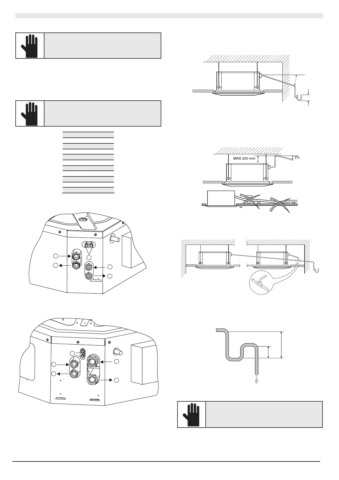
II.2.5.2 Setting up the condensate drain
For the condensate to flow correctly, the drain pipe must have a
downward 2% i nclinati on wit h n o bottle nec ks . Furth ermore, s et up a
siphon th at c an be inspected and is at least 50 mm de ep s o as to
prevent odours from returning into the room.
50
2%
The water can be dr ained t o a level t ha t is 200 mm higher than (ma x)
the unit, as l ong as th e tract of the asc en ding pip e is vertical an d
positioned in line with t he drain flange.
To drain the water to a higher level than that allowed, install an auxiliary
cond ens ate drain p ump with a collec tion tray and level reg ul ator. We
recommend models wit h a saf et y fl oat th at st ops th e wat er flo w if t he
pump malf uncti ons.
The pi pes mus t be co vered wit h anti-co ndensa te material, e.g.
pol yuret hane, polyprop yl ene, neopren e or 5-10 mm expa nded material.
If several u nits are installed in a ro o m, t he c on densat e drai n pi pes mus t
be installed as shown in the figure.
II.2.5.3 Setting up the water siphon
The co ndens ate drain s yste m mus t be set u p with an ad eq uat e sip hon
so as to prevent the infiltration of odours. The diagram below shows
how a water si phon is ins talle d.
50 mm
100 mm
Always set up or inst all a plug in t he l ower p art of the sip hon so as t o
allow a rapid disassembl y for t he cl eani ng operatio ns.
IMPORTANT !
Position the dra in pipe s so as not t o mechani ca ll y
stress the drain fitting of the unit.