SECTION II: INST ALL ATION AND MAINTEN ANCE
29
IMPORTANT !
DO NOT electrostatic or activated carbon filter kits
in presence of ducting towards the adjacent room.
Use a pencil t o trac e t he i nner Pol yst yre ne along the perimeters of th e
pre viousl y s heared s he et st eel, then use a c utter to c ut t he Pol yst yrene,
paying at te ntion not t o d amage t he c oil of the heat exc hang er at t he
bac k.
W
G
D
W
Wall
D
Door
G
Grid
It is not permitted to use the two pre-sheared side openings on the unit
simultaneousl y f or the air fl ow int o th e adjac ent roo m.
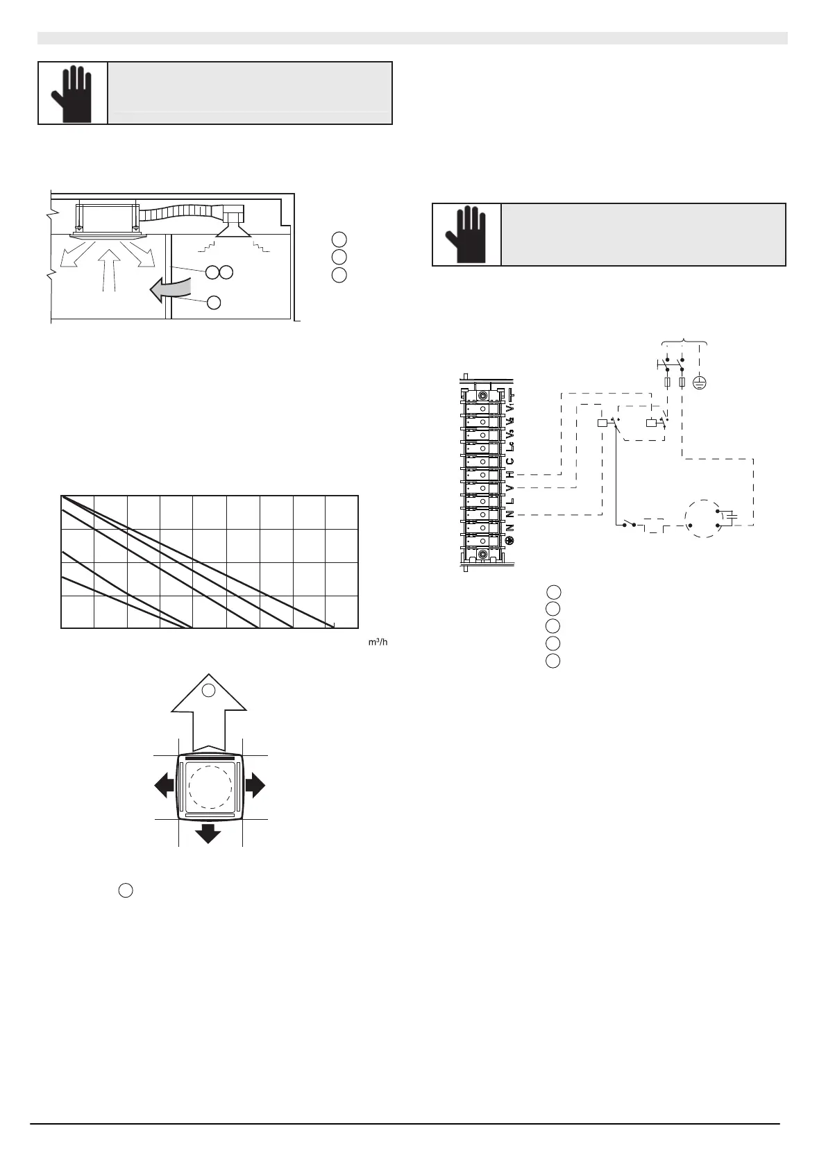
The “air flow in to the adjace nt room diagra m" hel ps det ermin e th e
leng th o f t he fl ow d ucts (also considering th e drop i n press ure b y mea ns
of air flow diff users, extern al air filters) a nd the incre ase i n noise due to
thes e ch annels.
Air flo w into the adjacent room diagram (one closed vent)
If t wo vents are cl osed, t he air flow rat e t owards t he adj ace nt ro om is
50% higher th an th at gen erat ed wit h 1 cl ose d ve nt (eq ual static c ou nter
pressure)
30
20
10
0
0
100
200
300 400
51/61
26
41
410
111
86
40
p (Pa)
Qa
(
)
4
p Static pressure availa ble
Qa Air flow r ate
4
Flow c han nel i nto th e adjace nt roo m
II.2.4.2 Outdoor fresh air
Remove t he precut sh eet metal and inst all the air c ontrol device b y
fixing it t o t he unit frame.
Use material (purchas ed l ocall y) th at is s uitabl e f or a c ontin uo us
tempera ture of 60 °C. The ducts c an be made of pol yester pipe (with a
steel s piral core) or made of c orrug ated al umini um, co vered ext ernall y
with anti-cond ens ate material (fibr eglass 12 - 25 mm t hic k).
Once i nstallati on is c omplet e, t he non-insul ated surf aces of t he duc ts
must be co vered wit h a nti-con densat e ins ulating mat erial (e.g . 6 mm
expa nded ne oprene).
IMPORTANT !
Failure to compl y with these instruction s can cause
dripping due to the conden sation. The Manufacturer
cannot be held liable for an y d amage.
An a dditi onal fan for th e int ake of out do or air (installed by the inst aller)
must be co nnec ted to th e t ermin al b oard as s hown i n the att ached
diag rams. T he fan fu nctions in parallel to the elec trothermal adj ust ment
val ve, f or it t o stop when the val ve closes .
230V~50Hz
1
2
3
4
5
1
Electrical b oard
2
Antifreeze ther mostat
3
Spe ed c ontr oller
4
Outdoor fan motor
5
230 V relay
For wint er functio ning wit h out do or air int ake, it is reco mmended t o
install a n anti-freez e th ermostat calibrate d to 2°C, wit h t he bulb plac ed
on t he water outl et pi pes, which i nterce pts t he ad ditio nal f an. The
out door air flo w rat e must be 10% less than t he tot al air flo w rate i n
order t o pre vent pro ble ms pertaini ng to t he fu nctioni ng or n oise.
The fres h air fl ow must be less than 10% of the t otal air flo w, t o a void
opera ting problems or ecc essi ve nois e. For higher air flow a "primary air
kit" K AP is a vaila ble whic h us es t he prepunc hed h ole f or air d ucting to
an adjac ent roo m and a baf fle s o that the fresh air is intro duc ed i nto th e
room through a diff user. I nst all an i ntake grid wit h an ins pecti on filter-
hold er frame on t he outside so as t o prevent d ust and leaves fro m
irreparabl y bl oc king the hea t exc ha nger coil of the unit.
If this filter is inst alled, a c hannel cl osing damper d oes no t n ee d to b e
installed during t he s hu tdown periods.