SECTION I: USER
22
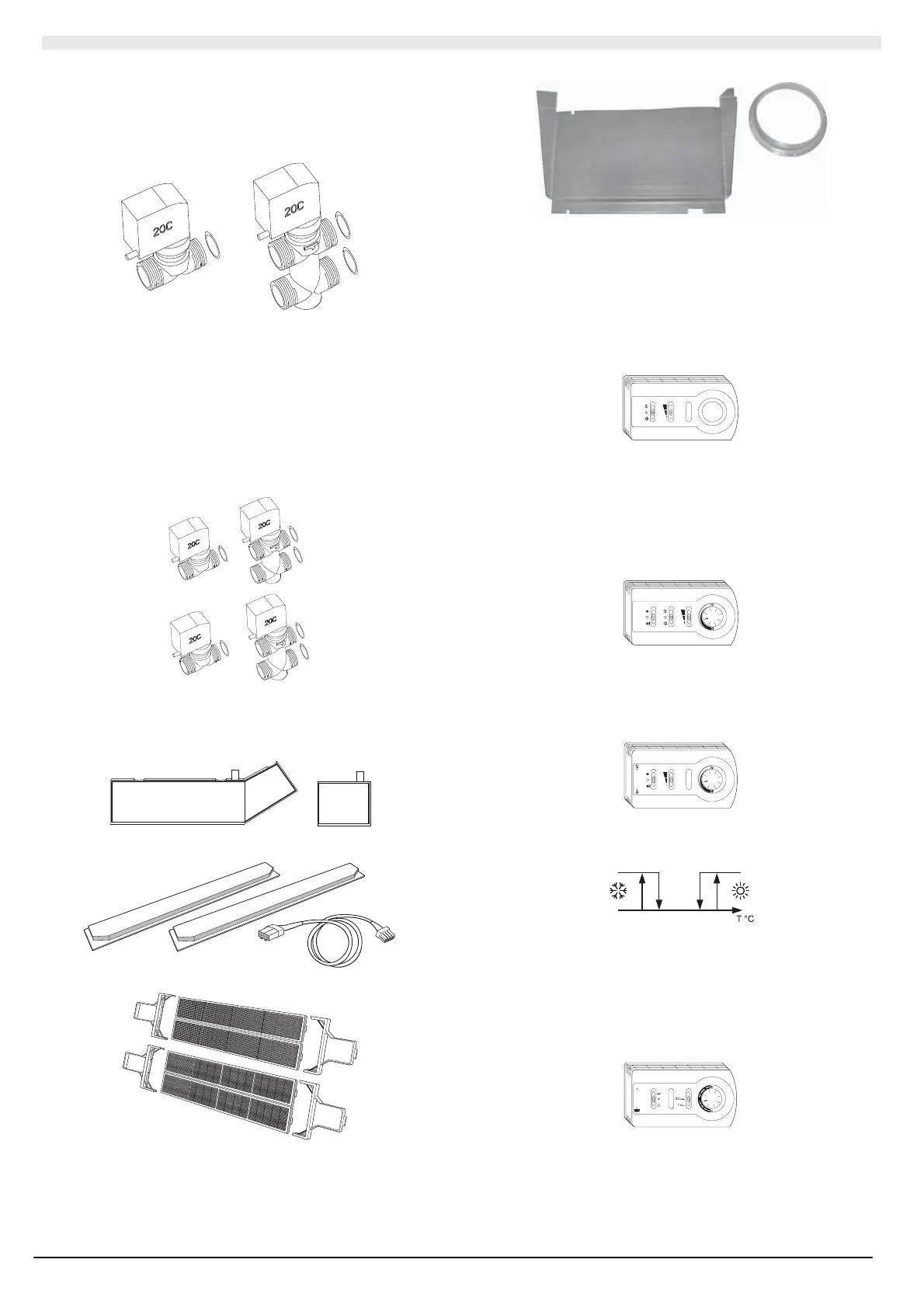
V2 - V3 (installed) – 2/ 3-wa y elec troval ve for 2-pip e s ystems c omplet e
with an insulation covering (the accessor y does not come with the
auxiliary condensate drain tray).
Models 26-41-51 (¾”)
Models 6 1-86-1 11 ( 1”)
KV2B4 - KV3B 4 (supplied separat ely) – 2 /3-way electro valve f or 4-
pipe sys tems. The c old side val ve is compl ete wit h an ins ulation
covering (the accessory does not come with the auxiliar y condensate
drain tra y).
V2B4 - V3B4 (installed) – 2/3- wa y electro val ve f or 4-pi pe s yst ems. The
cold side val ve is complete with an insulation covering (the accessory
does not come wit h t he auxiliary condensate drain tray).
Models 26-41-51 (¾” – ½”)
Models 6 1-86-1 11 ( 1” - ¾”)
KVA (supplied separately) - Auxiliary condensate drain tray.
26-41- 51 61-86- 111
KCB (supplied sep aratel y) - Flo w closur e slots.
KFFE (supplied separ ately) - Passi ve electros tatic photoc at alytic filter.
KAP (supplied separately) – Primar y air kit.
I.2.1 STANDARD COMMANDS AND CONTROLS
(SUPPLIED SEPARATELY)
UTNC-EV has a number o f co mmands and controls t hat can b e
supplie d se paratel y, on request. Hereu nd er is th e list o f co mmands or
controls that can be combined with the UTNC-EV.
• KCV2 (supplied sep aratel y)
Panel with a 3-speed switch complete with a summer/off/ winter switch
and t he p ossibility of connecting the minimum thermostat externally. Wall
mounted.
(Dimensions 1 45 x 82 x 40 mm)
• KTCV2 (supplied sepa ratel y)
Control and adjustment panel including: off/continuous
ve ntilati on/t her most at ventilation switc h; ro om thermostat ;
summer/winter switch; speed switch; auxiliary contacts (230 Vac) to
control t he On/Off val ves in 2-pi pe s ystems, 2- pipe s ys tems with electric
resistance or 4- pipe systems with the possibility of connec ting th e
minimum thermostat externally.
Wall mounted.
(Dimensions 1 45 x 82 x 40 mm)
• KTCVA (supplied sep arat e l y)
Electronic control panel including: continuous/off/thermostat ventilation
switch; 3-speed switch; room thermost at; automatic summer/winter
switchover; red/green heating/cooling functioning LED; auxiliary contact
(230 Vac) to c ontrol the ON/OFF valve in 2-pip e s ystems. Wall mounted.
(Dimensions 1 45 x 82 x 40 mm)
The heating -cooling switchover occurs aut omatically via d etectio n of t he
water t emperature in the fan c oil upstream the val ve acc ording to the
following logic.
20 23 29 32
Stand-by
T = wat er te mperat ure
• KTCVR ( supplied sep arate l y)
Electronic c ontr ol pa nel i ncludi ng: on /off /elec tric resistanc e s witch;
aut omatic su mmer/ wint er switc ho ver; auto matic sp eed/mi nimum s pe ed
switch; comfort ±5°C adjustment knob; auxiliary contacts (230 Vac) to
control t he ON/OFF val ve in 2-pipe s yst ems, 2-pipe s yst ems wit h
electric resistance or 4-pipe s yst ems .
Minimum th ermostat functio n, destra tificatio n c ycle and dirt y filter signal.
Wall mounted.
0
(Dimensions 1 45 x 82 x 40 mm)