User manual: Installation and Operation of Direction Finder System RHOTHETA RT-600 / SAR-DF 517
- 13 -
might be disturbing the bearing indication after a quick change of course of the aircraft or vehicle. In this
case, the indicated bearing value lags by the real bearing value for about two seconds (for very weak
signals even longer). By pressing this push-button after a quick change of course, the display will show the
new bearing value without drag error. Additionally, the CLR Push-Button is used to activate specific
functions high-lighted in the menu below the button:
(5) >STORE< push-button: Without function except if a special function is high-lighted in the menu line of the
display.
(6) >REPEAT< Push-button, when pressed, showing the last valid bearing value with corresponding receiving
level.
(7) >PAGE< Rotary switch to leave the DF mode in order to switch to the MEMORY (MEM) Page / Mode.
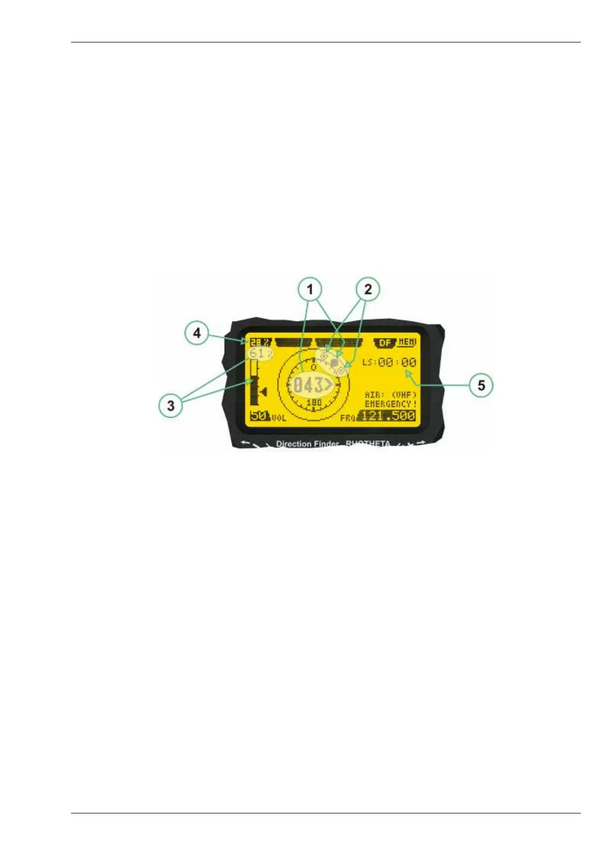
2.2.2 Standard Display in Bearing Mode
Display in Bearing Mode
(
1) >Relative Bearing value<, by means of a sophisticated averaging procedure, a steady display is
accomplished, either as graphic display or as text in the range of 0°… 359°. (0° corresponds to bearin g
direct ahead).
(2) >Spread<, maximum deviation of un-averaged bearing values. This is an indicator of bearing quality. The
wider the range between the directions of maximum deviation, the worse the received signal is. As a result
of the excellent averaging procedure, even with a spread of 45°, good bearing results are achieved.
(3) >Receiving level< (field strength) of the signal as a relative percentage value, visualized as bar-graph
indication and as decimal value. Even without a received signal a certain noise level may be displayed.
(4) >Squelch level< (independently adjustable and stored for each frequency). Squelch level is indicated as
marker at the Signal Strength Bar-Graph or as direct relative level value. A usable bearing analysis can
only be achieved if the squelch level is above the noise level (without received signal). If the antenna unit
is placed close a heavily disturbing electronic devices, the squelch level has to be raised, thus making the
direction finder being less sensitive. In receive modes where the squelch level is set automatically, an “A”
above the marker indicates the “Autosquelch” functionality.
(5) >Last Signal< timer showing the time since a signal has been received for the last time (i.e. since a signal
has been stronger than the squelch level). Values are “minutes:seconds”.