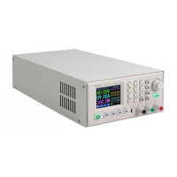
5) Cut the track and prepare pads.
Cut as shown in the image above.
Scrape off some of the solder
mask to expose bare copper.
Use a continuity checker to confirm the
new island of copper is not shorted to
ground.
Tin both pads in preparation soldering.
(As shown to right)
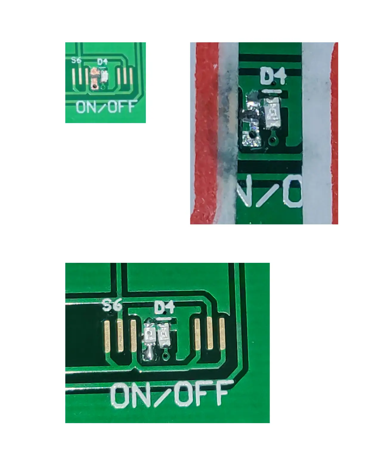
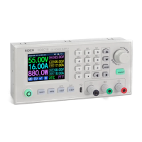
6) Solder in new Red LED.
Ensure the new LED is
in the same orientation
as the existing LED.
(This image also
shows the next step
completed, as seen
from the front of the
PCB.)