and fully retract the support bars into the power drive
housing.
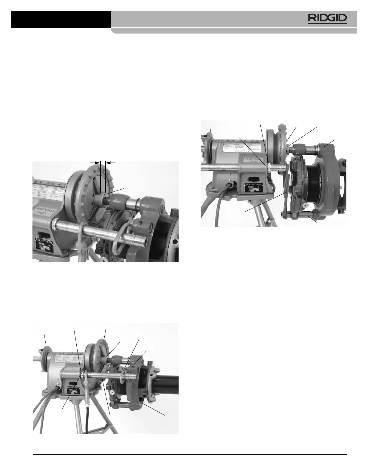
2. Use appropriate equipment to lift the geared thread-
er and place over the end of the pipe orienting one
jaw of work-holder upward. Lifting by hand must be
done by at least two people utilizing the carrying
handles. Be aware that the 141 weighs 93 pounds (42
kg) and the 161 weighs 158 pounds (72 kg). Leave
approximately
3
/
4
" (19 mm) of the drive bar exposed in
front of the chuck to allow space for oiling
(Figure 12)
.
Securely tighten chuck jaws into three “V” shaped
grooves in the head of drive bar. Close the rear cen-
tering head onto drive bar. Make sure that the geared
threader and power drive are stable and secure.
Figure 12 – Locating Drive Bar To Allow Oiling Space
3. Model 141 – Loosen set screw in geared threader
attachment boss. Install the 758 loop into boss and
tighten setscrew to retain loop. Pull switch side support
bar forward and through the 758 loop and secure in
place with the retaining ring assembly
(Figure 13)
.
Figure 13 – Model 141 Geared Threader Close-Coupled
to Power Drive
11
Model 141/161 Receding Geared Threaders
Model 161 – Remove setscrew (plug) from threader
guide post. Place the 346 support arms inside the
ends of the Power Drive support bars. Pull out the
Power Drive support bars so the ends of 346 support
arms align with the end of 161 Threader guide post
and retain with bolt and washer. Tighten the retaining
ring assemblies on the Power Drive support bars to
hold in place
(Figure 14).
Figure 14 – Model 161 Geared Threader Close-Coupled
to Power Drive
Setting up 535, 300 Compact or 1233
Close coupled to 141 Geared Threader
This method can also be used with the 300 and 300A
Power Drives when equipped with a carriage. Do not
use geared threaders with machines on folding stands.
Stand must be in good condition.
1. Loosen setscrew in geared threader attachment boss.
Install the 768 Drive Link into boss and tighten set -
screw to retain
(Figure 15)
. Do not over tighten – the
drive link should rotate freely.
2. If using a 535M with the high clearance carriage,
place the leveling saddle on the carriage as shown in
Figure 16
.
3. Use appropriate equipment to lift the geared threader
and place. Lifting by hand must be done by at least
two people utilizing the carrying handles, be aware that
the 141 weighs 93 pounds (42 kg) and the 161 weighs
158 pounds (72 kg). Leave approximately
3
/
4
" of the
drive bar exposed in front of the chuck to allow space
for oiling
(Figure 12).
Securely tighten chuck jaws
into three “V” shaped grooves in the head of drive bar.
Close the rear centering device onto drive bar. Make
sure that the geared threader and power drive are sta-
ble and secure.
Centering
Device
Retaining Ring
Assembly
Chuck
Handwheel
No. 758
Loop
Set Screw
Collar Set
Screw
Support Bar
No. 141
Geared
Threader
844
V Groove
3/4" (19 mm)
Centering
Head
Retaining Ring
Assembly
Set Screw
Chuck
Handwheel
Drive Bar
Geared
Threader
Guide Post
Bolt & Washer
No. 346
Support
Arm (2)