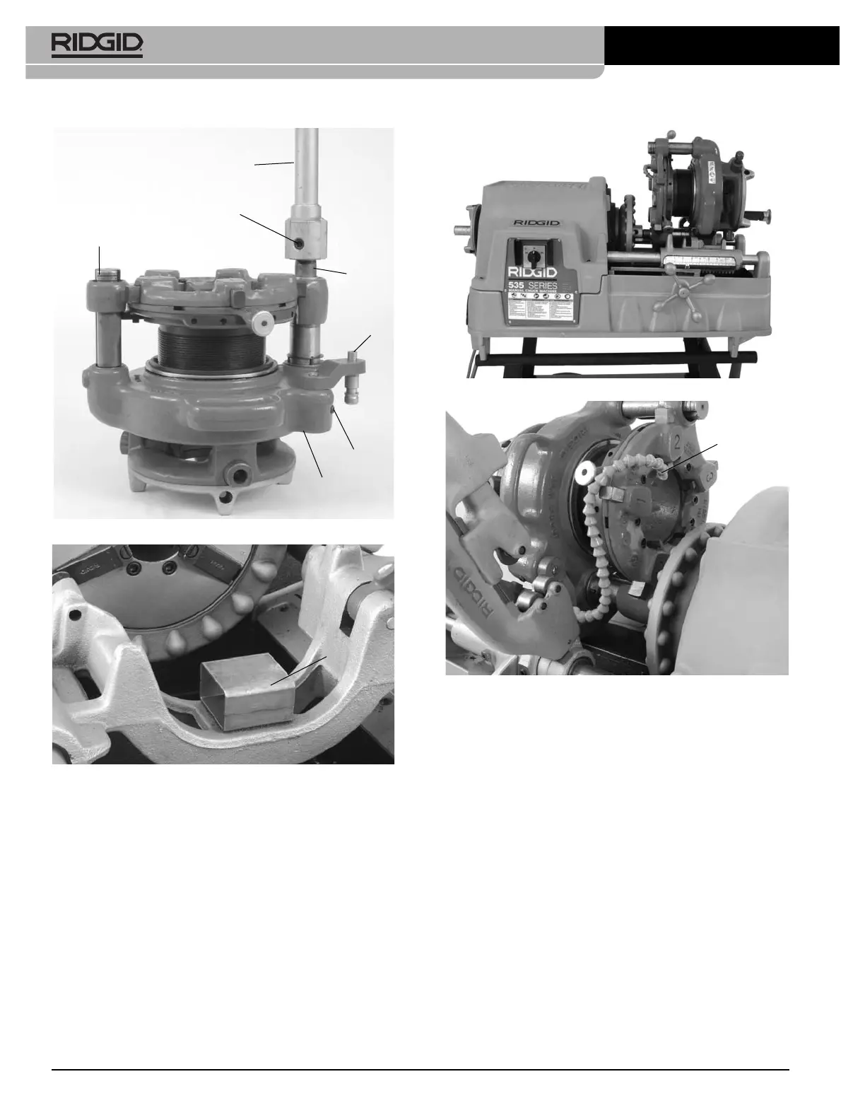
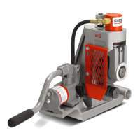
Figure 15 – 844 Drive Bar and 768 Drive Link Installed
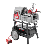
Figure 16 – Saddle on 535 Carriage
4. Align the post of 768 drive link with the die head
mounting hole in the carriage and fully insert by mov-
ing the carriage. Tighten the drive link set screw to hold
in place. Make sure that the geared threader and
threading machine are stable and secure
(Figure 17)
.
5. On machines with oiling systems, install the flexible oil
spout on drive link and route so nozzle applies oil
between chaser #1 and 2.
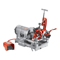
Figure 17 – Geared Threader Close-Coupled To 535
Figure 18 – Flexible Oil Spout Routing
Setting up 535A Close Coupled to 141
Geared Threader
1. Place the leveling saddle on the carriage as shown in
Figure 16.
2. Install the flexible oil spout on 268 drive link.
3. Loosen set screw in geared threader attachment
boss.
4. From the rear of machine, install the drive bar through
the spindle tube to the cover (jaws must be fully
open). A counterclockwise rotation of the drive bar is
required.
5. Using at least two people or appropriate equipment, lift
the geared threader, and place on the leveling saddle
with the driveshaft of the geared thread lined up with
the driveshaft in the threading machine.
12
Model 141/161 Receding Geared Threaders
141 Geared Threader
Set Screw (2)
No. 844 Drive Bar
Drive
Shaft
Set Screw
768 Drive
Link
Attachment
Boss
Leveling
Saddle
Oil Spout
Between Dies
1 and 2