The 141 and 161 can be powered in a variety of ways,
including operation by hand or with various RIDGID
Threading Machines and Power Drives.
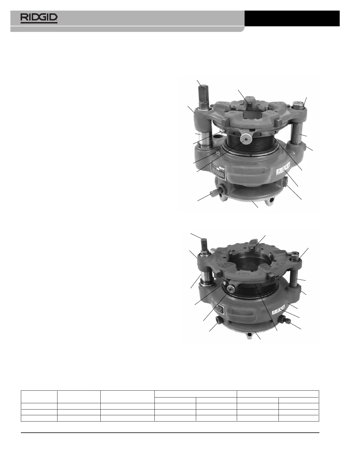
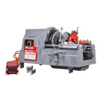
Figure 1 – Model 141 Receding Geared Threader
Figure 2 – Model 161 Receding Geared Threader
• Follow instructions on proper use of this machine.
Do not use for other purposes such as drilling
holes or turning winches. Other uses or modifying
this power drive for other applications may increase the
risk of serious injury.
• Read and understand the instructions and warn-
ings for all equipment being used including Thread -
ing Machines and Power Drives before operating
the Geared Threaders. Failure to follow all warnings
and instructions may result in property damage and/or
serious injury.
• Do not use this machine if the foot switch is bro-
ken or missing. Foot switch is a safety device that
provides better control by letting you shut off the motor
in various emergency situations by removing your
foot from the switch. For example: if clothing should
become caught in the machine, the high torque will
continue pulling you into the machine. The clothing
itself can bind around your arm or other body parts with
enough force to crush or break bones.
The EC Declaration of Conformity (890-011-320.10) will
accompany this manual as a separate booklet when
required.
If you have any question concerning this RIDGID
®
product:
– Contact your local RIDGID distributor.
– Visit www.RIDGID.com to find your local RIDGID con-
tact point.
– Contact RIDGID Technical Services Department at
rtctechservices@emerson.com, or in the U.S. and
Canada call (800) 519-3456.
Description, Specifications and
Standard Equipment
Description
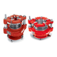
The RIDGID
®
Model 141 and 161 Receding Geared
Thread ers are designed to thread 2
1
/
2
" to 4" and 4" to 6"
pipe, respectively. A cam type workholder is used to grip
the pipe while the die head cuts the threads. A clutch is
included to prevent jamming at the end of the thread.
The threaders can be used for both tapered and straight
right hand threads with a simple adjustment. See specifi-
cations for NPT and BSPT versions.
4
Model 141/161 Receding Geared Threaders
Model No. Thread Type Threads Per Inch
Nominal Capacity Weight
inch mm lb kg
141 NPT 8 2½ to 4 65 to 100 93 42.2
141 BSPT 11 2½ to 4 65 to 100 93 42.2
161 NPT 8 4 to 6 100 to 150 158 71.7
Die (Set of 5)
Thread
Size Marks
Guide
Post
Gear Case
Selector Plate
Die Head
Stop
Screw
Pinion
Sleeve
Guide
Post
Die
(Set of 5)
Drive Shaft
Clamp Screw
Cam Plate
Knob (2)
Thread Size
Marks )
Selector
Plate
Die Head
Stop
Screw
Work Holder Jaws (3)
Pinion
Sleeve
Grease
Fitting
Work Holder
Work Holder
Jaws (2)
Warning
Label
Guide
Post
Screw
Specifications
Drive Shaft
Work Holder
Guide
Post
Screw
Clamp
Screw
Warning
Label
Cam Plate
Knob (2)