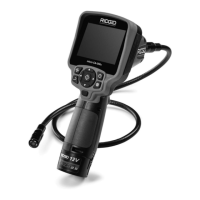
micro CA-25 Inspection Camera
7
1. Make sure the unit is OFF.
2. Remove the battery holder and inspect
it and batteries for signs of dam age. Re-
place batteries if necessary. Do not use
inspection camera if batteries are dam-
aged.
3. Clean any oil, grease or dirt from the
e quip ment. This aids inspection and helps
prevent the tool from slipping from your
grip.
4. Inspect micro CA-25 Inspection Camera
for any broken, warn, miss ing, misaligned
or binding parts or any condition which
may prevent safe and normal operation.
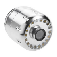
5. Inspect the camera head lens for con-
densation. To avoid damaging the unit,
do not use the camera if condensation
forms inside the lens. Let the water evap-
orate before using.
6. Inspect the full length of the cable for
cracks or damage. A damaged cable
could allow water to enter the unit and
increase the risk of electrical shock.
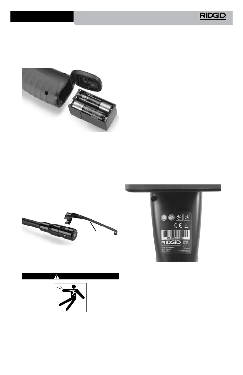
7. Check that the warning label is present,
rmly attached and readable.
Figure 6 – Warning Label
8. If any issues are found during the inspec-
tion, do not use the inspection camera
until it has been properly serviced.
9. With dry hands, re-install the battery
hold er, making sure to fully insert.
10. Press and Hold the Power Button for 1
second. Once the camera is ready an im-
age will appear. If the unit does not oper-
ate properly, try changing the batteries.
11. Press and Hold the Power Button for 1
second to turn the unit OFF.
3. Insert battery compartment into inspec-
tion camera terminal end rst. The com-
partment will only go in one way. Do not
force. Close the battery door, conrm
securely closed.
Figure 4 – Battery Compartment
Installing An Accessory
The three included accessories, (mirror, hook
and magnet) (Figure 1) all attach to the im-
ager head the same way.
To connect, hold the imager head as shown
in Figure 5. Slip the semicircle end of the
acces sory over the ats of the imager head as
shown in Figure 5. Then rotate the accessory
a 1/4 turn so the long arm of the accessory is
extending out as shown.
Figure 5 – Installing Accessories
Accessory
Pre-Operation Inspection
WARNING
Before each use, inspect your inspection
camera and correct any problems to reduce
the risk of serious injury from electric shock
and other causes and prevent tool damage.
 Loading...