16
Alignment (Adjustments)
WARNING: Cut material can be
thrown. Eyes can be permanently
damaged. Wear your safety gog-
gles.
NOTE: Before this saw is aligned or used,
a kerf must be cut into the table insert at
0° bevel. Our Quality Control Audit Proce-
dure requires us to cut through the inserts
before they leave our factory.
To cut through an uncut insert:
1. Plug in the power cord.
1. Turn the saw on by actuating the trigger
switch.
2. Lower the blade to full depth while cut-
ting through the table insert.
3. Release the trigger switch and allow
the blade to come to a complete stop.
4. Repeat this procedure at 45° bevel.
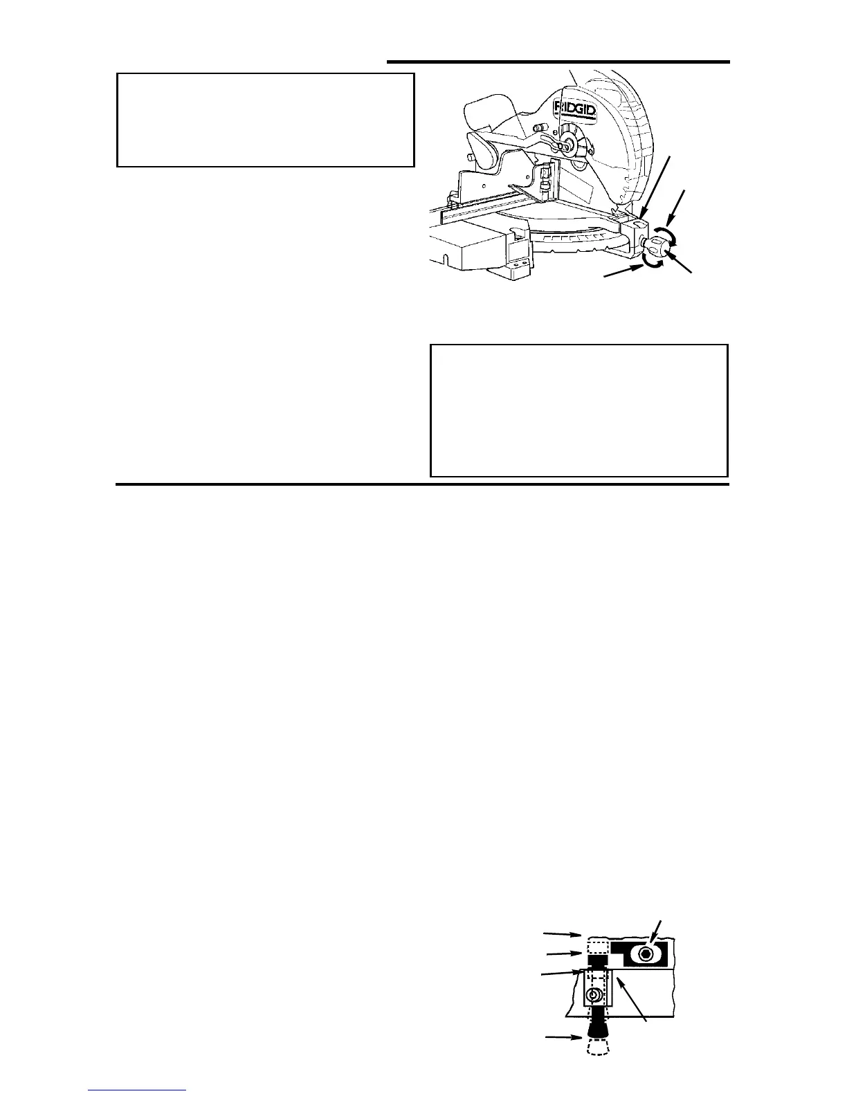
Tighten
Spring
Loosen
Handle
5. Unplug the power cord before starting
alignment procedure.
WARNING: To reduce the risk of
injury from unexpected starting
or electrical shock, do not plug
the saw in. The power cord must
remain unplugged whenever you
are working on the saw.
Step One: Blade Square to Table (Bevel Alignment)
NOTE: The miter saw was assembled,
aligned, and inspected before shipment.
Alignment should be checked and any
adjustments made to insure accurate cuts.
1. Check miter lock knob setting. The
miter lock knob should be at the 0°
position. To reset the miter angle, turn
the miter lock knob counter clockwise
and press down the index spring, move
to 0° miter and retighten knob.
2. Lower the blade and engage the lock
pin. Use a combination square to check
blade squareness to table. If the blade
does not contact the full length of the
square, (see illustration) follow the
alignment procedure.
a. Loosen bevel lock knob.
b. Grasping carrying handle, move the
cutting head left or right until blade
makes contact with the full length of
the square.
NOTE: If you cannot get to 0° bevel, the
bevel stop may be in your way. Adjust the
bevelstop(SeeStepd)soyoumay
achieve 0° bevel.
c. Tighten the bevel lock knob.
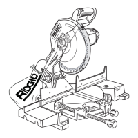
d. Loosen the 0° bevel stop mounting
screw and push the stop against the
pin. Retighten the stop mounting
wrench. Slide the indicator under the
Phillipsheadscrewtolineupexactly
with the 0° bevel mark on the bevel
scale. Retighten the indicator screw.
e. Loosen bevel lock knob and tilt the
power head to 45° bevel and check
the 45° bevel stop. The bevel indica-
tor should be on the 45° mark, the
45° bevel stop should be in full con-
tact with the 45° bevel stop screw,
and the blade should contact the full
length of the square. This adjustment
sets the 45° and crown molding
stops.
3. If adjustment is necessary, repeat steps
2a - 2d for the 45°/crown molding bevel
stop.
Index/
By-Pass Pin
By-Pass
0°, 45° Index
0°, CM Index
Bevel Index
Mechanism
Bevel Stop
Mounting Screw