33
20035512
GB
Appendix - Firing rate on basis of air density
C
The firing rate of the burner shown in the manual is valid for a
room temperature of 20°C and an altitude of 0m above sea lev-
el (barometric pressure around 1013 mbar).
It may be that a burner has to operate with combustive air at a
higher temperature and/or higher altitudes.
The heating of the air and the increase in altitude produce the
same effect: the expansion of the air volume (i.e. the reduction
of its density).
The delivery of the burner fan remains essentially the same,
but the oxygen per m
3
of air, and the thrust (discharge head)
of the fan are reduced.
It is therefore important to know if the maximum output re-
quested from the burner at a determinate combustion chamber
pressure remains within the firing rate of the burner even with
the changed temperature and altitude conditions.
To check it, proceed as follows:
1 -Find the corrective factor F (relating to the air temperature
and altitude of the system) in the table alongside.
2 -Divide the output Q required from the burner by F to obtain
the equivalent output Qe:
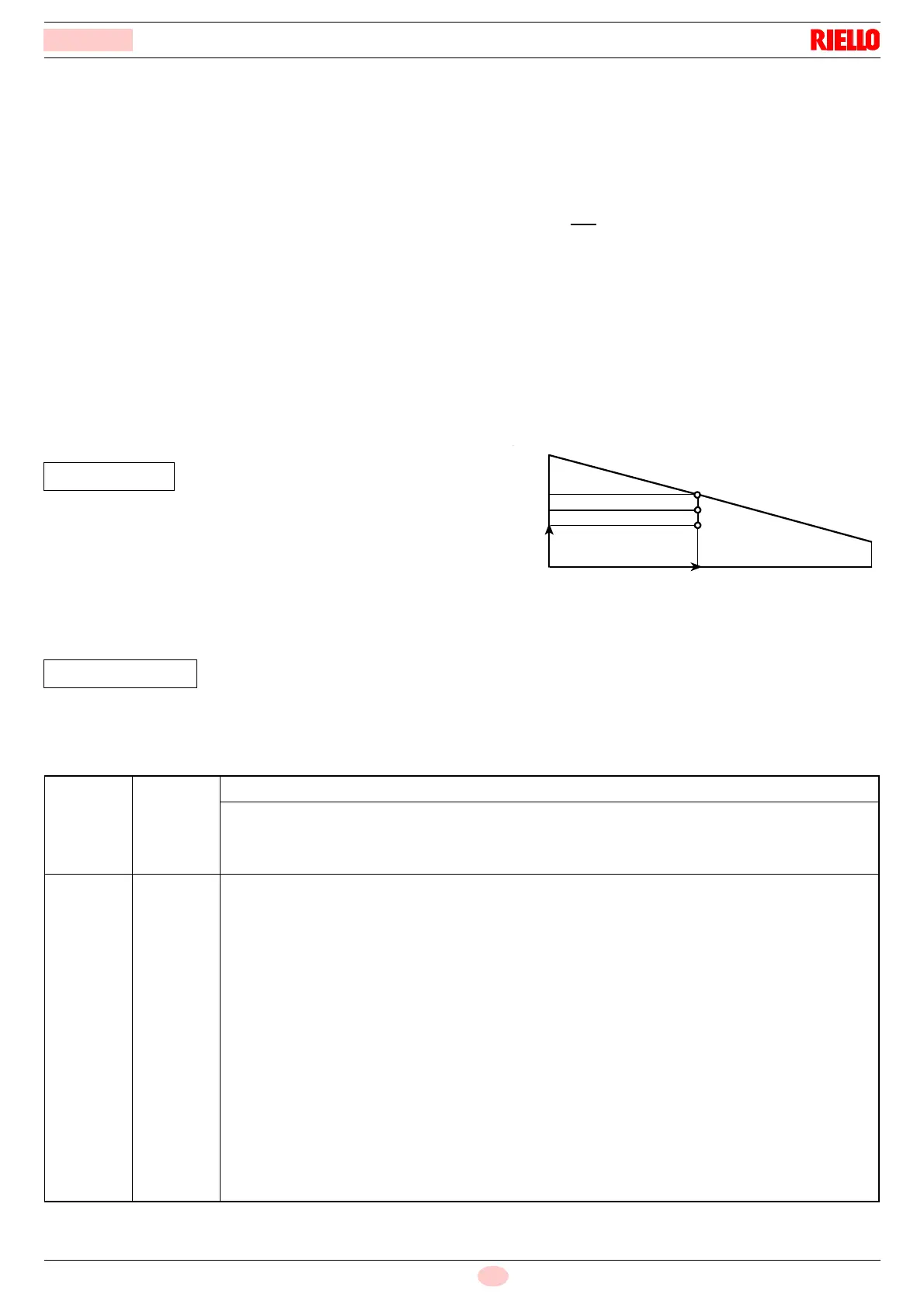
3 -In the firing rate of the burner, mark the work point identified
by:
Qe = equivalent output
H1 = pressure in combustion chamber
point A that must remain within the firing rate (Fig. 40).
4 -Trace a vertical line from point A, Fig. 40, and find the max-
imum pressure H2 of the firing rate.
5 -Multiply H2 by F to obtain the maximum lowered pressure
H3 of the firing rate
If H3 is greater than H1, as in Fig. 40, the burner can produce
the delivery requested.
If H3 is less than H1, it is necessary to reduce the burner out-
put. The reduction in output is accompanied by a reduction in
the combustion chamber pressure:
Qr = reduced output
H1r = reduced pressure
Example, 5% reduction in output:
Qr = Q x 0.95
H1r = H1 x (0.95)
2
With the new values - Qr and H1r - repeat steps 2 - 5.
Warning:
the combustion head should be adjusted in relation to the
equivalent output Qe.
Qe = Q : F (kW)
H3 = H2 x F (mbar)
Fig. 40
Qe
A
H1
H2
H3
D388
kW
mbar
Altitude
Average
barometric
pressure
F
Air temperature °C
m. above sea
level
mbar 0 5 10 15 20 25 30 40
0
100
200
300
400
500
600
700
800
900
1000
1200
1400
1600
1800
2000
2400
2800
3200
3600
4000
1013
1000
989
978
966
955
944
932
921
910
898
878
856
836
815
794
755
714
675
635
616
1.087
1.073
1.061
1.050
1.037
1.025
1.013
1.000
0.988
0.977
0.964
0.942
0.919
0.897
0.875
0.852
0.810
0.766
0.724
0.682
0.661
1.068
1.054
1.042
1.031
1.018
1.007
0.995
0.982
0.971
0.959
0.946
0.925
0.902
0.881
0.859
0.837
0.796
0.753
0.711
0.669
0.649
1.049
1.035
1.024
1.013
1.000
0.989
0.977
0.965
0.954
0.942
0.930
0.909
0.886
0.866
0.844
0.822
0.782
0.739
0.699
0.657
0.638
1.031
1.017
1.006
0.995
0.983
0.972
0.960
0.948
0.937
0.926
0.914
0.893
0.871
0.851
0.829
0.808
0.768
0.726
0.687
0.646
0.627
1.013
1.000
0.
989
0.978
0.
966
0.955
0.944
0.932
0.921
0.910
0.898
0.878
0.856
0.836
0.815
0.794
0.755
0.714
0.675
0.635
0.616
0.996
0.983
0.972
0.962
0.950
0.939
0.928
0.916
0.906
0.895
0.883
0.863
0.842
0.822
0.801
0.781
0.742
0.702
0.664
0.624
0.606
0.980
0.967
0.956
0.946
0.934
0.923
0.913
0.901
0.891
0.880
0.868
0.849
0.828
0.808
0.788
0.768
0.730
0.690
0.653
0.614
0.596
0.948
0.936
0.926
0.916
0.904
0.894
0.884
0.872
0.862
0.852
0.841
0.822
0.801
0.783
0.763
0.743
0.707
0.668
0.632
0.594
0.577
 Loading...