20026897
8
Technical description of the burner
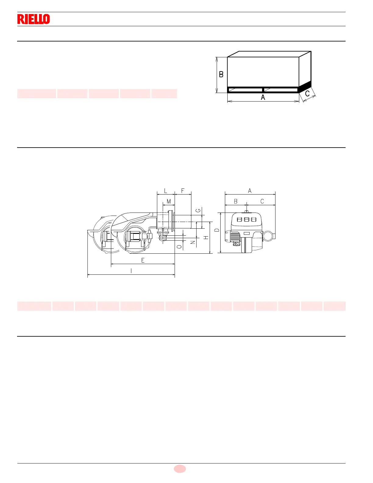
3.5 Packaging - weight - Approximate measurements
The burners are skid mounted. Outer dimensions of packaging are
indicated in (Tab. B).
The weight of the burner complete with packaging is indicated in
(Tab. B).
Tab. B
3.6 Burner dimensions
The maximum dimensions of the burners are given in (Fig. 3).
Inspection of the combustion head requires the burner to be
opened and the rear part withdrawn on the slide bars.
The maximum dimension of the burner when open, without casing,
is give in measurement I.
Tab. C
3.7 Standard equipment
Gas train flange . . . . . . . . . . . . . . . . . . . . . . . . . . . . . . . . . . . No. 1
Flange gasket. . . . . . . . . . . . . . . . . . . . . . . . . . . . . . . . . . . . . No. 1
Flange fixing screws. . . . . . . . . . . . . . . . . . . . . . . . . . . . . . . . No. 4
Adaptor G 1/4” / 1/4” NPT . . . . . . . . . . . . . . . . . . . . . . . . . . . No. 1
Seal for adaptor . . . . . . . . . . . . . . . . . . . . . . . . . . . . . . . . . . . No. 1
Connector for adaptor . . . . . . . . . . . . . . . . . . . . . . . . . . . . . . No. 1
Circular sector . . . . . . . . . . . . . . . . . . . . . . . . . . . . . . . . . . . . No. 4
Instruction booklet . . . . . . . . . . . . . . . . . . . . . . . . . . . . . . . . . No. 1
inch A B C lbs
RLS 160/E 52
3
/
4“
28
1
/
2“
34
1
/
4“
210
Model ABCDEFGH I LMNO
RLS 160/E 33
3
/
16“
14
13
/
32“
18
25
/
32“
23
9
/
16“
41
13
/
32“
14
11
/
16“
8
11
/
16“
16
15
/
16“
54“ 9
3
/
4”
5
31
/
32”
8
23
/
32“
2“