20026897
30
Start-up, calibration and operation of the burner
5.6 Final calibration of the pressure switches
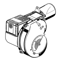
5.6.1 Air pressure switch
Adjust the air pressure switch after having performed all other burn-
er adjustments with the air pressure switch set to the start of the
scale (Fig. 40).
With the burner operating at min. output, increase adjustment pres-
sure by slowly turning the relative dial clockwise until the burner
locks out.
Then turn the dial anti-clockwise by about 20% of the set point and
repeat burner starting to ensure it is correct.
If the burner locks out again, turn the dial anti-clockwise a little bit
more.
During these operations it may be useful to measure the air pres-
sure with a pressure gauge.
The connection of the pressure gauge is shown in Fig. 41.
The standard configuration is that with the air pressure switch con-
nected in absolute mode.
Note the presence of a “T” connection, not supplied.
The air pressure switch may operate in "differential" operation in
two pipe system.
If a negative pressure in the combustion chamber during pre-purg-
ing prevents the air pressure switch from switching, switching may
be obtained by fitting a second pipe between the air pressure
switch and the suction inlet of the fan. In such a manner the air
pressure switch operates as differential pressure switch.
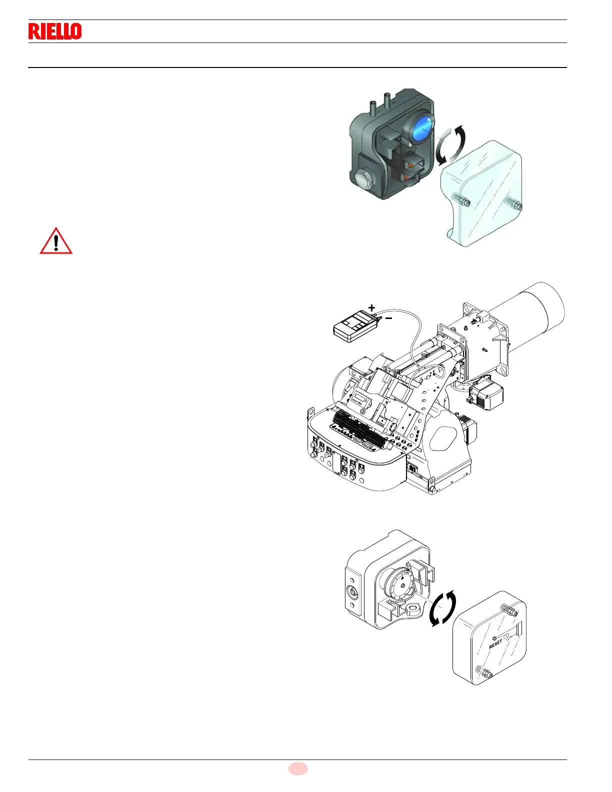
5.6.2 Maximum gas pressure switch
Adjust the maximum gas pressure switch after having performed all
other burner adjustments with the maximum gas pressure switch
set to the end of the scale (Fig. 42).
With the burner operating at MAX output, reduce the adjustment
pressure by slowly turning the adjustment dial anticlockwise until
the burner locks out.
Then turn the dial clockwise by 0.8” WC and repeat burner firing.
If the burner locks out again, turn the dial again clockwise by
0.4” WC.
As a rule, the air pressure switch must prevent the
formation of CO. To check this, insert a combustion
analyser into the chimney, slowly close the fan suc-
tion inlet (for example with cardboard) and check
that the burner locks out, before the CO in the
fumes exceeds 400 ppm.