Installation
17
20026897
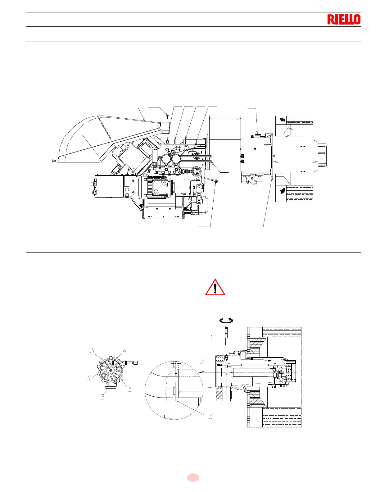
4.4 Securing the burner to the boiler
Detach the combustion head from the burner, (Fig. 12):
disconnect the oil pipes by unscrewing the two connectors 6);
loosen the 4 screws 3) and remove the cover 1);
disengage the swivel coupling 14) from the graduated sector;
remove the screws 2) from the slide bars 5);
remove the 2 screws 4) and pull the burner back on slide bars
5) by about 4”;
install the extension bars 31) Fig. 1, page 7 and re-screw the
screws 2) including the safety plate 15);
disconnect the electrode wires and then pull the burner com-
pletely off the slide bars.
4.5 Combustion head calibration
At this point check, whether the maximum delivery of the burner in
2nd stage operation is contained in area A or in area B of the firing
rate. See (Fig. 4, page 9).
If it is in area B then no operation is required.
If, on the other hand, it is in area A, pre-set the combustion head
as below indicated:
remove the screw 1)(Fig. 13) and extract the internal part 2);
replace the 4 circular sectors 3) by unsCrewing the relevant
screws, with the circular sectors supplied with the burner.
Do not remove the circular sector 4.