Technical description of the burner
7
20026897
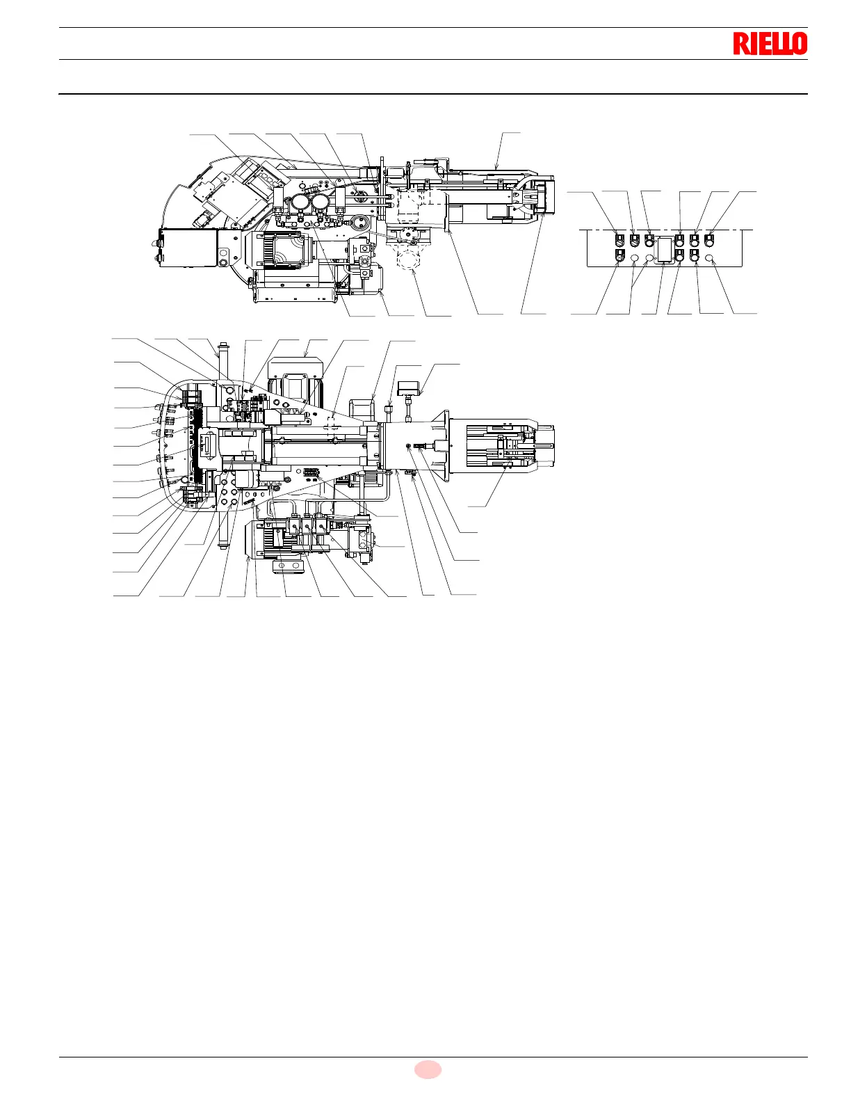
3.4 Burner description
1 Combustion head
2 Ignition electrodes
3 Screw for combustion head adjustment
4Sleeve
5Fan motor
6 RWF 40 modulator (with analog output 4-20 mA)
7 Fan motor contactor and thermal relay with reset button
8 UV scanner
9 Terminal strip x 1
10 Holes for cables grommets for electrical wirings, accessories
and power supply (to be carried out by the installer)
11 Selectors and light signals
12 Operator panel with LCD display
13 Flame inspection window
14 Low air pressure switch (differential operating type)
15 Slide bars for opening the burner and inspecting the combus-
tion head
16 Safety oil solenoid valve
17 Valve assembly with pressure regulator on nozzle return
18 Gas pressure test point and head fixing screw
19 Air pressure test point
20 Air servomotor
21 Pump motor
22 Low oil pressure switch
23 Pilot attachment
24 Pump
25 Gas train flange
26 Boiler mounting flange
27 Flame stability disk
28 Screw securing fan to sleeve
29 Max. gas pressure switch
30 Ignition transformers “TA2” (for gas operation)
31 Lifting rings and extention bars
32 Oil/gas actuator
33 High oil pressure switch
34 Ignition transformer “TA1” (for oil operation)
35 Terminal strip “X2”
36 Timer module and relay “KO1”
37 Timer module and relay “KG1”
38 “K3” relay
39 “K1” relay
40 “KG2” relay
41 “K5” relay
42 “K2” relay
43 Horn
44 Auxiliary fuse
45 Switch “OFF - ON”
46 Switch “LOCAL REMOTE”
47 Button “ALARM SILENCE”
48 Switch “OIL - OFF GAS”
49 Signal “POWER ON”
50 Signal “CALL FOR HEAT
51 Signal “ALARM ON”
52 Signal “IGNITION ON”
53 Signal “FUEL ON”
54 Optional holes
55 Ground terminals
56 Pump motor contactor and thermal relay with reset button
57 Delivery oil solenoid valve
58 Return oil solenoid valve
59 DIN bar for fuse holder step-down transformer and OCI
412.10
1
13
15
22
25
26
28
27
17
20
33
2
3
4
36
5
7
8
55
10
14
16
18
32
55
23
29
30
19
44
34
37
38
9
43
39
40
41
42
55
21
3156
12
59
11
10
24
35
5857
45
46
47
49
50
48
54 6 52
53
54
51