11
INSTALLATION DIAGRAMS
If you decide to bring together in one manifold the discharges
of each unit, the diameter of the pipe to be used for one or
two units Condexa Pro3 IN-EXT series connected in series is Ø200
mm (see Figure 8). For cascade installations where there are
more than two machines the diameter of the exhaust manifold
must be properly sizing, or simply connect up to two Condexa
Pro3 IN-EXT using multiple lines Ø200 separated.
Maximum Pipe Length (m)
Installed power
(kW)
with Ø 160 with Ø 200
230 60 -
345 60 -
460 40 60
575 25 60
690 - 60
805 - 55
920 - 40
1035 - 35
1150 - 25
Figure 8
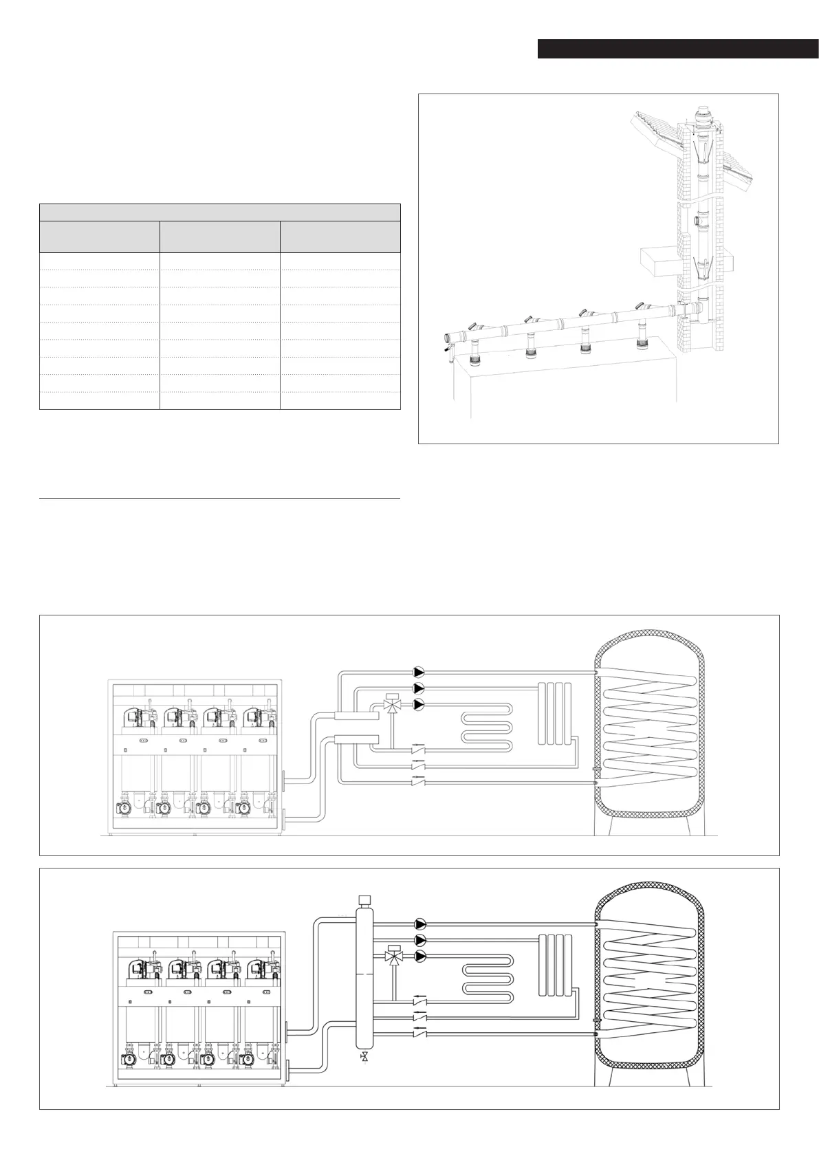
5 INSTALLATION DIAGRAMS
An installation diagram must generally be adapted to the man-
ufacturing characteristics of the relevant heating unit, with the
purpose of exploiting the boiler potentials to the full and main-
tain the entire installation efcient for as long as possible.
The Figure 9 is shown an installation without a mixing element,
in Figure 10 is shown a installation with a mixing element.
Figure 9
Figure 10
 Loading...