Do you have a question about the Riello multipower MPW Series and is the answer not in the manual?
Read the specific safety manual before any operation on the Modular UPS System.
Details regarding the company's efforts in analysing environmental issues and product materials.
Information on handling toxic and dangerous waste materials according to current legislation.
Highlights key features like efficiency, scalability, availability, and easy control of the MPW modular UPS.
Diagrams of the UPS cabinet's front and back, detailing key components.
Diagrams of the UPS cabinet's top and bottom, detailing cable entry and mobility features.
Diagrams of the PWC 130 front with modules inserted and extracted.
Diagrams of the PWC 130 rear, showing internal components and connection areas.
Diagrams of the PWC 300 front with modules inserted and extracted.
Diagrams of the PWC 300 rear, showing internal components and connection areas.
Diagram of the BTC 170 front, showing battery units, switch, and PSU.
Diagram of the BTC 170 rear, showing power connections.
Diagrams of the CBC 130 front with modules inserted and extracted.
Diagrams of the CBC 130 rear, showing internal components and connection areas.
Diagram of the Connectivity Panel with labeled MCU, PSU, MU, and expansion slots.
Details on network and SA connection ports, and their usage.
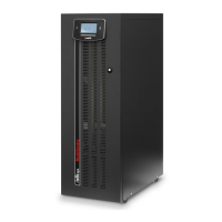
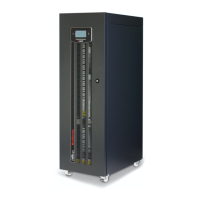
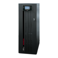
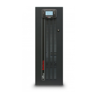
General description of UPS systems, cabinet types, and maintenance recommendations.
Operation in double conversion mode providing maximum protection.
Automatic switch to battery power when AC network fails or deviates from tolerances.
Load powered directly by AC supply, input interference affects the load.
Optimizes efficiency by using bypass supply, switching to online mode on failure.
Generates a fixed output frequency different from the input frequency.
Improves efficiency at low loads by placing unused PMs in low consumption state.
Procedure to switch the system to Manual Bypass, ensuring continuous load power.
Procedure to switch the system back from Manual Bypass to normal operation.
Details on cabinet capacity for Power Modules and Bypass Module.
Explanation of parallel PMs for reliability and load sharing.
Role of the Bypass Module as central automatic bypass.
Information on connecting multiple Power Cabinets in parallel for increased power.
Schematic illustrating the internal wiring of the Modular UPS Power Cabinet.
Details on cabinet structure, battery unit supervision, and SWBATT switch.
Table defining minimum battery shelves based on non-redundant PMs.
Schematic illustrating the internal wiring of the Modular Battery Cabinet.
Details on cabinet capacity for PMs, BM, battery shelves, and redundancy.
Information on internal/external batteries, supervision system, and SWBATT switch.
Table defining minimum battery shelves based on non-redundant PMs.
Schematic illustrating the internal wiring of the Modular UPS Combo Cabinet.
Note referring to a specific installation manual for cabinet setup.
List of modules and units that support quick maintenance and expandability.
Schematic illustrating the individual components and wiring of a Power Module.
Diagram and description of the PM interface panel and status LEDs.
Explanation of the meaning of various icons and status indicators on the interface panel.
Description of communication ports (PORT S, PORT M) reserved for service personnel.
Step-by-step guide for inserting a Power Module into the cabinet.
Step-by-step guide for extracting a Power Module from the cabinet.
Description and wiring diagram of the Bypass Module.
Diagrams showing BM interface panels and controls for different cabinet types.
Explanation of status indicators and their meanings for the Bypass Module.
Step-by-step guide for extracting a Bypass Module from the cabinet.
Step-by-step guide for inserting a Bypass Module into the cabinet.
Description of MU's role in monitoring cabinets and system status.
Diagram and explanation of MU interface panel and status indicators.
Instructions for inserting and extracting the MU from its slot.
Description of PSU's role in powering cabinet electronics.
Diagram and description of the PSU interface panel and status indicators.
Instructions for inserting and extracting the PSU from its slot.
Description of MCU's role in monitoring and system control via touch screen.
Instructions for inserting and extracting the MCU from its slot.
Description of the Battery Unit containing 12V battery packs.
Step-by-step guide for inserting a Battery Unit into the battery cabinet.
Step-by-step guide for extracting a Battery Unit from the battery cabinet.
Safety warning regarding dangerous voltage and contacting service agents.
Guidelines for maintaining battery efficiency and durability through charging and storage.
Description of the touch screen display's capabilities for monitoring and control.
Explanation of the status bar displaying page title, power, date, and time.
Description of icons representing system input, output, bypass, and battery status.
Explanation of color coding for icons indicating system status (grey, light blue, blue, orange, red).
Meaning of color coding for energy flow bands (blue for bypass, light blue for inverter).
Explanation of how the graphic bar represents PMs configured for load supply.
Guidance on adding redundant PMs for increased system reliability.
Diagrams illustrating different redundancy cases based on PM status and load.
Description of display areas for System, Cabinet, Power Module, and Alarm list status.
Description of display areas for Mains Input, Battery, Bypass Input, and Output values.
Explanation of HOME, PREVIOUS, and SEND E-MAIL functions.
Description of menu expansion/reduction and detail section keys.
Illustration of different states for sliding switches (Off, On, Locked, Unavailable).
Explanation of symbols used for touch, swipe, and graphical elements on the display.
Example view of the Home page showing normal operation status.
Example view of the Home page showing battery operation status.
Example view of the Home page showing load on bypass status.
Example view of Home page with manual bypass active.
Example view showing redundancy alarm signal on Home page.
Example view of Home page with EPO active.
Explanation of key icons: alarms, data processing, and power off status.
Display of voltage, current, and frequency for the system input.
Display of voltage, current, power, and frequency for the system output.
Display of battery voltage, current, temperature, and autonomy.
Detailed display of battery status, including residual Ah.
Display of voltage and frequency for the system bypass line.
Detailed display of output voltage, current, and power.
Display of status for Power or Combo cabinets (A, B, C, D).
Display of status for connected Battery Cabinets (1, 2, 3...).
Further display of Battery Cabinet status.
How anomalies in cabinets are highlighted on the status page.
Page showing system name, localization, and contact details.
Details on hostname, DHCP, IP address, and MAC address.
User-configurable parameters like voltage, frequency, mode, and autorestart.
Display of firmware versions for modules and battery cabinets.
Display of serial numbers for individual modules and battery cabinets.
Display of status for modules within Cabinet A (PMs, BM, MU).
Display of electrical values for Power Cabinet 130 modules.
Display of electrical values for Combo Cabinet 130 modules.
Display of battery values for the Battery Cabinet.
Display of voltage, current, and frequency for PM mains input.
Display of battery voltage, current, temperature, and autonomy for PM.
Display of voltage and frequency for PM bypass input.
Display of voltage, current, power, and frequency for PM output.
Display of bypass input voltage and frequency.
Display of bypass output voltage, current, and power.
Display of status for various switches monitored by the MU.
Display of temperature sensor readings for cabinet and battery.
Display of MU switch and sensor status for Combo Cabinets.
Display of battery unit voltage and current for Combo Cabinets.
Display of MU switch and sensor status for Battery Cabinets.
Display of battery unit voltage and current for Battery Cabinets.
Display of status and electrical values for a selected Battery Unit Array.
Description of User, Power User, and Expert access levels.
Notes on accessing configuration and changes based on access level.
Requirement of 'Power User' access for Command Panel.
Procedure to switch the system ON using the Command Panel.
Description of the system start-up sequence with progress bar.
Procedure to switch the system OFF using the Command Panel.
Procedure to execute the battery test using the Command Panel.
Process of selecting a Power Module for ON/OFF operation.
Procedure to switch individual Power Modules ON or OFF.
Procedure to view the system event log file.
Procedure to export log files (events, data, configuration) to a USB drive.
Procedure for managing the Emergency Power Off (EPO) condition.
Overview of main setup categories: Language, Time, Scheduler, Mail, Network, General.
Interface for selecting the system menu language.
Pages for setting the system date, time, and timezone.
Setting up the NTP server for automatic system clock synchronization.
Configuration for automatic battery tests and email notifications.
Setting up SMTP server, sender details, and authentication.
Configuring email addresses for receiving alarm messages.
Customizing email subject, header, and footer.
Configuration of system identification name and TCP/IP protocol.
Setting static IP address, Netmask, Gateway, and DNS.
Enabling UDP/HTTP and configuring port passwords.
Setting system name, location, and contact person.
Procedure for setting or changing user access level passwords.
Configuring homepage inactivity timeout and enabling/disabling the buzzer.
Explanation of different buzzer sounds indicating UPS status and anomalies.
Description of optional accessories like Air Filter and IP 21 kit.
Information on monitoring battery room temperature using the ASB card.
Description of the Connectivity Panel and its user interfaces.
Details on embedded Ethernet and expansion slots for communication cards.
Protocols available via Ethernet: HTTP, SMTP, UDP.
SNMP and Modbus TCP protocols via Netman 204.
Note on protocol availability when Netman 204 is fitted.
Detailed procedures for switching the MPW system ON.
Steps for direct system ON command, including sequence and verification.
Steps for system ON via static bypass, including sequence and verification.
Steps to switch to Manual Bypass using static bypass.
Steps for direct manual bypass switch operation.
Procedure to switch from Manual Bypass back to normal inverter operation.
Procedure for replacing a PM when redundancy is available.
Procedure for replacing a PM when redundancy is not available.
Procedure for replacing a Bypass Module during online mode.
Procedure for replacing MU, PSU, and MCU units without load interruption.
Procedure for replacing a Battery Unit when the system is not on battery mode.
List of status messages for the MPW system and their severity.
List of status messages for Power Modules and their severity.
Categorized list of Power Module alarm codes (Command, Warning, Anomaly, Fault).
Continuation of Power Module alarm codes.
Further Power Module alarm codes related to Lock and Fault conditions.
List of status messages for the Bypass Module and their severity.
Categorized list of Bypass Module alarm codes (Command, Warning, Anomaly, Fault, Lock).
List of status messages for the Monitoring Unit and their severity.
Categorized list of Monitoring Unit alarm codes (Command, Warning, Anomaly, Fault).
List of alarm codes for Battery Units.
Technical data for UPS input voltage, frequency, and power factor.
Technical data for bypass nominal power, voltage, and frequency.
Technical data for battery configuration and characteristics.
Technical data for UPS output voltage, frequency, and stability.
Cabinet types, power module ratings, dimensions, weight, noise, and IP class.
| Overload Capacity | 125% for 10 minutes, 150% for 1 minute |
|---|---|
| Topology | Double Conversion Online |
| Frequency | 50/60 Hz |
| Battery Type | VRLA |
| Communication | RS232, USB, dry contacts |
| Parallel Operation | Up to 8 units |
| Operating Temperature | 0°C to 40°C |
| Relative Humidity | Up to 95% non-condensing |
| Cooling | Forced air |