20141254
10
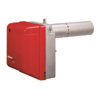
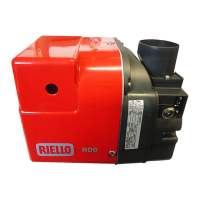
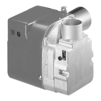
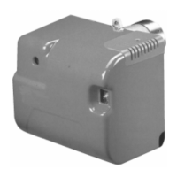
Technical description of the burner
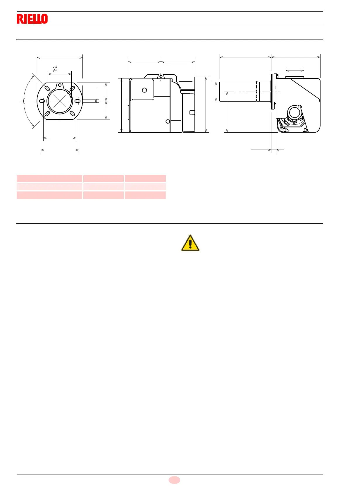
4.3 Overall dimensions
Tab. B
4.4 Burner equipment
Screw and nuts for flange .................................................. No. 1
Screws and nuts for fixing the flange to the boiler ............. No. 4
Hexagonal wrench .............................................................. No. 1
Air intake (CF)..................................................................... No. 1
Installation, use and maintenance instructions ................... No. 1
Spare parts list .................................................................... No. 1
225
135
153
233
29
170
B
209
75
A
83 83
189
45°
45°
150
156
11
106
Model A B
RDB2.2R BG1 BLU 21 80 230
RDB2.2R BG1 BLU 26 89 230
RDB2.2R BG3 BLU 36 89 230
In case of use with light oil containing bio blend, it
will be essential to use flexible oil lines suitable for
biofuel use.
Please contact the manufacturer for further infor-
mation.