20141254
18
Installation
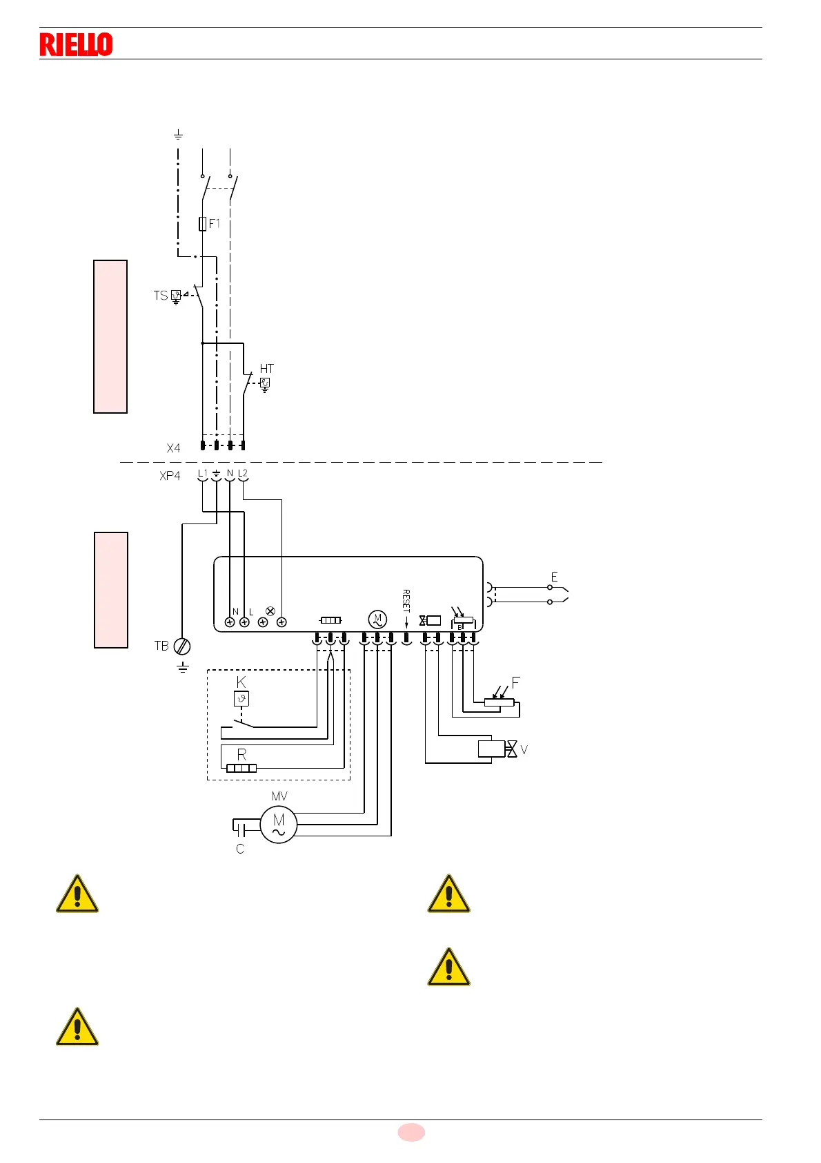
5.11.2 Electrical diagram
~50 Hz - 230V
L
N
20142270
Fig. 13
Key (Fig. 13)
C: Capacitor
E: Electrodes
F: Flame sensor
F1: 5AT 250Vac Fuse
HT: Heat request thermostat
MV: Fan motor
TB: Burner-earth
TS: Safety thermostat
V: Oil valve
X4: 4-pin plug
XP4: 4-pin socket
K: Thermostat for start-up approval after preheating
R: Heater
CARRIED OUT
BY THE INSTALLER
CARRIED OUT
IN THE FACTORY
Green/Yellow
CONTROL BOX
HEAT
Main switch
DEMAND
Black
White
Blue
Blue
Brown
Black
Do not invert the neutral with the phase in the
electrical supply line.
Check that the electrical supply of the burner
corresponds to that shown on the identifica-
tion label and in this manual.
The section of the conductors must be at
least 1 mm
2
. (Unless requested otherwise by
local standards and legislation).
Test the burner by checking the shut-down of the
burner by opening the thermostats and the lockout
by darkening the flame sensor.
If the cover is still on, remove it and proceed with
the electric wiring following the wiring diagrams.
Use flexible cables in compliance with EN 60 335-
1 standards.
This control box has a post-purging function
Do not replace it with other versions!