20033333
12
Technical description of the burner
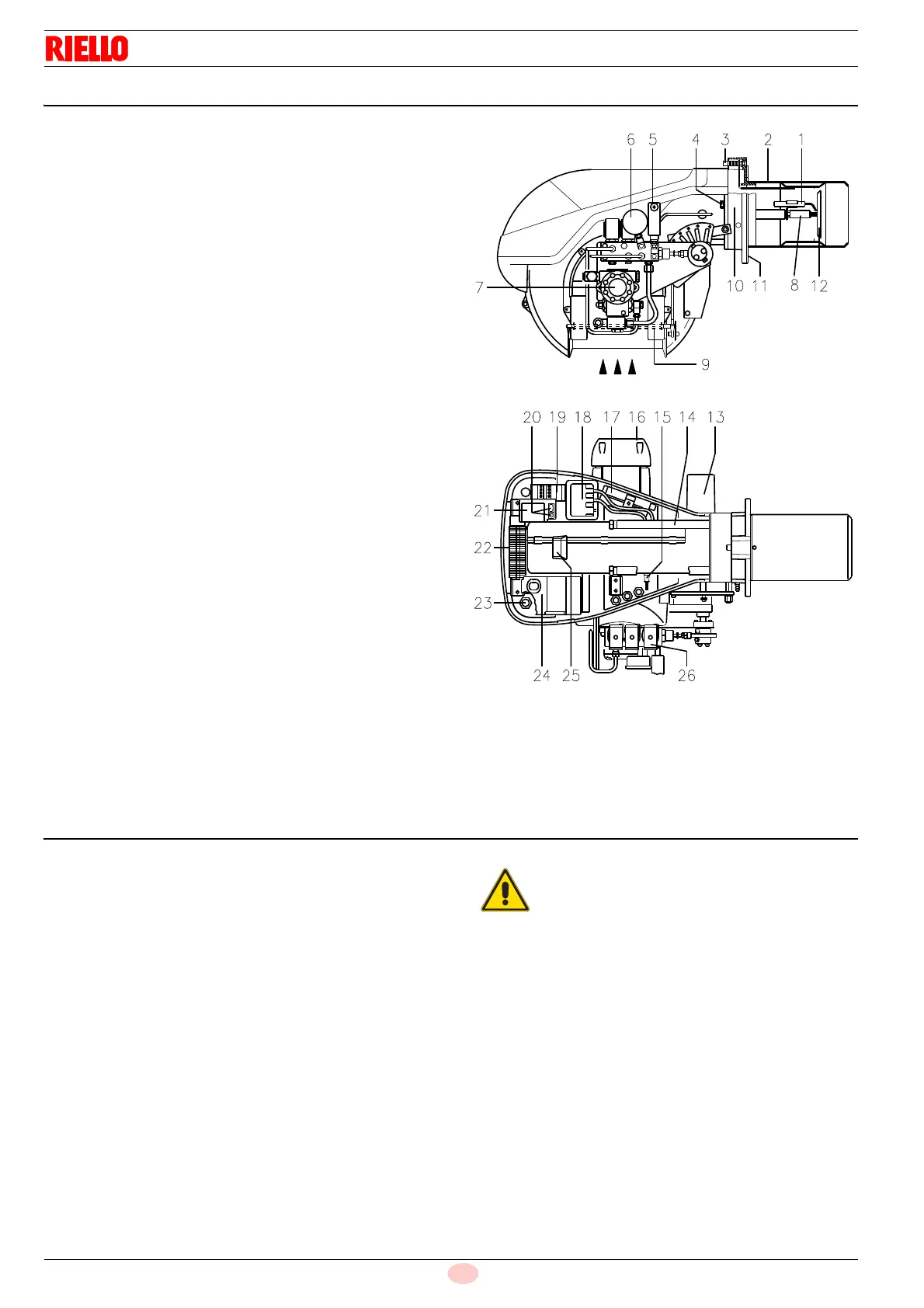
4.8 Burner description
1 Ignition electrodes
2 Combustion head
3 Screw for combustion head adjustment
4 Screw for fixing fan to flange
5 Oil pressure switch
6 Pressure gauge for pressure on nozzle return
7Pump
8 Non-drip nozzle holder
9 Air gate valve
10 Fan pressure test point
11 Boiler mounting flange
12 Flame stability disk
13 Servomotor, provides adjustment of fuel delivery regulator
and of air gate valve.
When the burner is not operating the air gate valve is fully
closed in order to reduce to a minimum heat dispersion from
the boiler due to the flue draught which draws air from the
fan suction inlet.
14 Slide bars for opening the burner and inspecting the com-
bustion head
15 Photocell for flame presence control
16 Electrical motor
17 Extensions for slide bars 14)
18 Ignition transformer
19 Motor contactor and thermal cut-out with reset button
20 Power switch for different operations:
automatic - manual - off
Button for: power increase - power reduction.
21 Bracket for mounting power regulator RWF40
22 Terminal strip
23 Fairleads for electrical connections by installer
24 Control box with lock-out pilot light and lock-out reset button
25 Flame inspection window
26 Valve assembly with pressure regulator on nozzle return
Two types of burner failure may occur:
Control Box Lock-out:
if the control box 24)(Fig. 4) pushbutton lights up, it indicates that
the burner is in lock-out. To reset, press the pushbutton.
Motor trip:
release by pressing the pushbutton on thermal relay 19)(Fig. 4).
4.9 Standard equipment
2 - Hoses
2 - Gaskets for flexible hoses
2 - Nipples for flexible hoses
1 - Thermal insulation screen
4 Extensions 17)(Fig. 4) for slide bars 14)(Fig. 4) (for models
with 385 mm blast tube)
4 - Screws to secure the burner flange to the boiler: M 12 x 35
1 - Instruction booklet
1 - Spare parts list
In case of use with gas oil containing up to 10%
Bio blend, it will be essential to use flexible oil
lines suitable for bio fuel use.
Please contact Riello for further information.