20033333
22
Start-up, calibration and operation of the burner
7.1 Notes on safety for the first start-up
7.2 Burner firing
Close load controls and set switch 1)(Fig. 23) to “MAN”.
After burner firing a complete burner adjustment should be per-
formed.
7.3 Burner calibration
The optimum calibration of the burner requires an analysis of the
flue gases at the boiler outlet.
Adjust successively:
– Combustion head
– Servomotor
– MAX burner output
– MIN burner output
– Intermediate outputs between MAX and MIN output
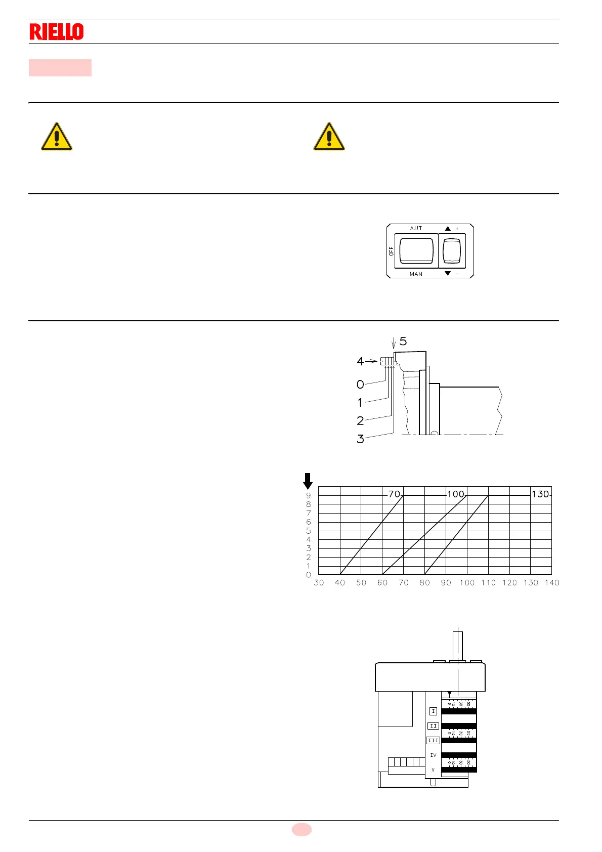
7.3.1 Combustion head setting
The setting of the combustion head depends exclusively on the
maximum burner delivery at which it will be operating.
Turn screw 4)(Fig. 24) until the notch shown in diagram (Fig. 25)
is level with the front surface of flange 5)(Fig. 24).
Example:
RL 70/M, maximum light oil delivery = 50 kg/h.
Diagram (Fig. 25) indicates that for a delivery of 50 kg/h the burn-
er requires the combustion head to be set to approx. three notch-
es, as shown in Fig. 24.
7.3.2 Servomotor
The servomotor (Fig. 26) provides simultaneous adjustment of
the air gate valve, by means of the variable profile cam and the
pressure regulator.
The servomotor rotates through 130° in 42 seconds. Do not alter
the factory setting for the 5 cams; simply check that they are set
as indicated below:
Cam I: 130°
Limits rotation toward maximum position.
Cam II:0°
Limits rotation toward the minimum position. When
the burner is shut down the air gate valve must be
closed: 0°.
Cam III:20°
Adjusts the ignition position and the MIN output.
Cam IV-V: not utilized.
7 Start-up, calibration and operation of the burner
The first start-up of the burner must be carried out
by qualified personnel, as indicated in this manual
and in compliance with the standards and regula-
tions of the laws in force.
Check the correct working of the adjustment, com-
mand and safety devices.
Fig. 25
Notches
Max gas oil delivery - kg/h
D1223