15
20033333
Installation
5.7 Blast tube length
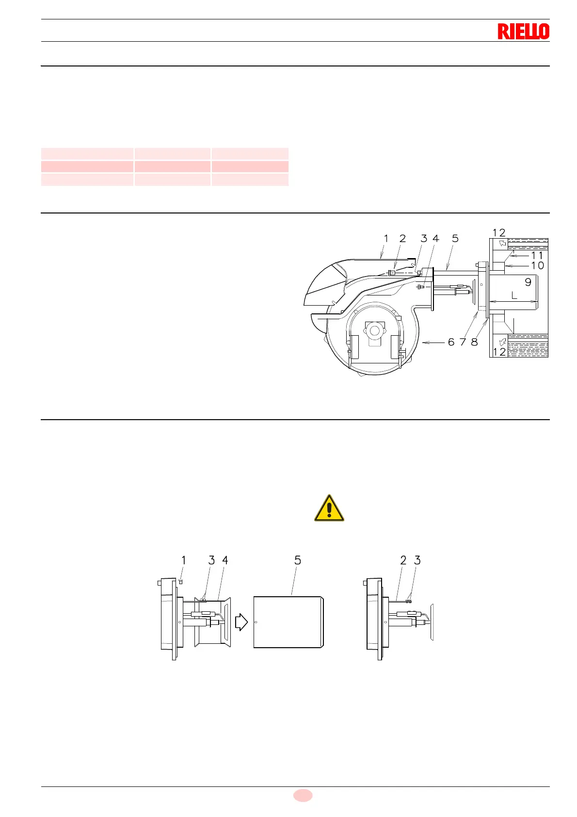
The length of the blast tube 9)(Fig. 8) must be selected according
to the indications provided by the manufacturer of the boiler, and
in any case it must be greater than the thickness of the boiler door
complete with its fettling.
The range of lengths available, L (mm), is as follows:
For boilers with front flue passes 12)(Fig. 8) or flame inversion
chambers, protective fettling in refractory material 10) must be in-
serted between the boiler fettling 11) and the blast tube 9).
This protective fettling must not compromise the extraction of the
blast tube.
For boilers having a water-cooled front the refractory fettling 10)-
11) is not required unless it is expressly requested by the boiler
manufacturer.
5.8 Securing the burner to the boiler
Disassemble the blast tube 9)(Fig. 8) from the burner 6) by pro-
ceeding as follows:
loosen the four screws 3) and remove the cover 1);
remove the screws 2) from the two slide bars 5);
remove the two screws 4) fixing the burner 6) to the flange
7);
withdraw the blast tube 9) complete with flange 7) and slide
bars 5).
5.9 Combustion head calibration
At this point check, for model RL 130/M, whether the maximum
delivery of the burner in 2
nd
stage operation is contained in area
B or in area C of the firing rate. See page 11.
If it is in area B then no operation is required.
If, on the other hand, it is in area C:
– unscrew the screws 1)(Fig. 9) and disassemble the blast tube
5);
– unscrew the screws 3) and remove the shutter 4);
– tighten the screws 3) on the rod 2);
– now refit the blast tube 5) and the screws 1).
Once this operation has been carried out (if it was required), se-
cure flange 7)(Fig. 8) to the boiler plate interposing the supplied
gasket 8).
Use the 4 screws provided after having protected the thread with
antiscruffing products.
Blast tube 9)(Fig. 8) Short Long
RL 70/M 272 385
RL 100/M 272 385
RL 130/M 272 385
The burner-boiler seal must be airtight.