20033333
16
Installation
5.10 Nozzle installation
The burner complies with the emission requirements of the
EN 267 standard.
In order to guarantee that emissions do not vary, recommended
and/or alternative nozzles specified by Riello in the Instruction
and warning booklet should be used.
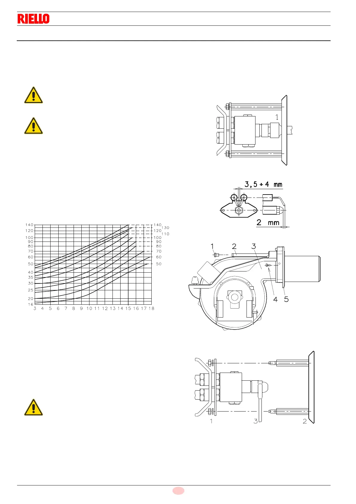
In case an intermediate delivery between the two values indicat-
ed in the diagram (Fig. 10) is required, a nozzle with higher deliv-
ery must be chosen.
Delivery reduction will be obtained by means of the pressure reg-
ulator.
5.10.1 Recommended nozzles
Type A3 or A4 Bergonzo nozzles - 45° angle.
5.10.2 Nozzle assembly
At this stage of installation the burner is still disassembled from
the blast tube; it is therefore possible to fit the nozzle with the box
spanner 1)(Fig. 11), fitting the spanner through the central hole in
the flame stability disk.
Make sure that the electrodes are positioned as shown in Fig. 12.
Finally remount the burner 3)(Fig. 13) on the slide bars 2) and
slide it up to the flange 5), keeping it slightly raised to prevent the
flame stability disk from pressing against the blast tube.
Tighten the screws 1) on the slide bars 2) and screw 4) that at-
taches the burner to the flange.
If it proves necessary to change a nozzle with the burner already
fitted to the boiler, proceed as outlined below:
retract the burner on its slide bars as shown in Fig. 8 at
page 15);
remove the nuts 1)(Fig. 14) and the disk 2);
use spanner 3)(Fig. 14) to change the nozzles.
It is advisable to replace nozzles every year
during regular maintenance operations.
The use of nozzles other than those specified by
Riello S.p.A. and inadequate regular maintenance
may result into emission limits non-conforming to
the values set forth by the regulations in force, and
in extremely serious cases, into potential hazards
to people and objects.
The manufacturing company shall not be liable for
any such damage arising from nonobservance of
the requirements contained in this manual.
Do not use any sealing products such as gaskets,
sealing compound, or tape.
Be careful to avoid damaging the nozzle sealing
seat.
Fig. 10
Return pressure - bar
Nozzle flow rate - kg/h
D1228