33
20033333
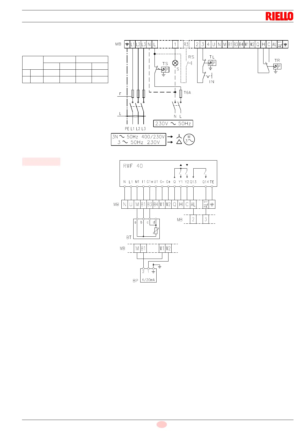
Appendix - Electrical panel layout
TO BE COMPLETED BY THE INSTALLER
Key to layout
CMV Motor contactor
LAL 1.25 Control box
FR Photocell
MB Terminal strip
MV Fan motor
PO Oil pressure switch
RT Thermal cut-out
S1 Power switch for different operations:
MAN = manual
AUT = automatic
OFF = off
S2 Button for:
– power reduction
+ power increase
SM Servomotor
TA Ignition transformer
TB Burner ground (earth) connection
VM Delivery pump valve
VS Delivery pump valve (safety valve)
VS1 Safety valve on return
VU Valve on nozzle return
BT Temperature probe
BP Pressure probe
IN Manual burner stop switch
MB Terminal strip
RS Remote lock-out reset button (if present)
S Remote lock-out signal
TL Limit control device system: this shuts down the burn-
er when the boiler temperature or pressure exceeds
the setpoint value.
TR High-low mode control device system: this controls
operating stages 1
st
and 2
nd
.
The TR load control is not required when the regulator
RWF40 is connected as its function is performed by
the regulator RWF40 itself.
TS Safety control device system: this operates when TL
is faulty.
Electrical connection three-phase
230/400V power supply
D866
Fig. 40
RL 70/M RL 100-130/M
230V 400V 230V 400V
F A T10 T6 T16 T10
Lmm
2
1.5 1.5 1.5 1.5
Fig. 41
RWF40
Power regulator RWF40 electrical
connection
D1910