20095042
8
Technical description of the burner
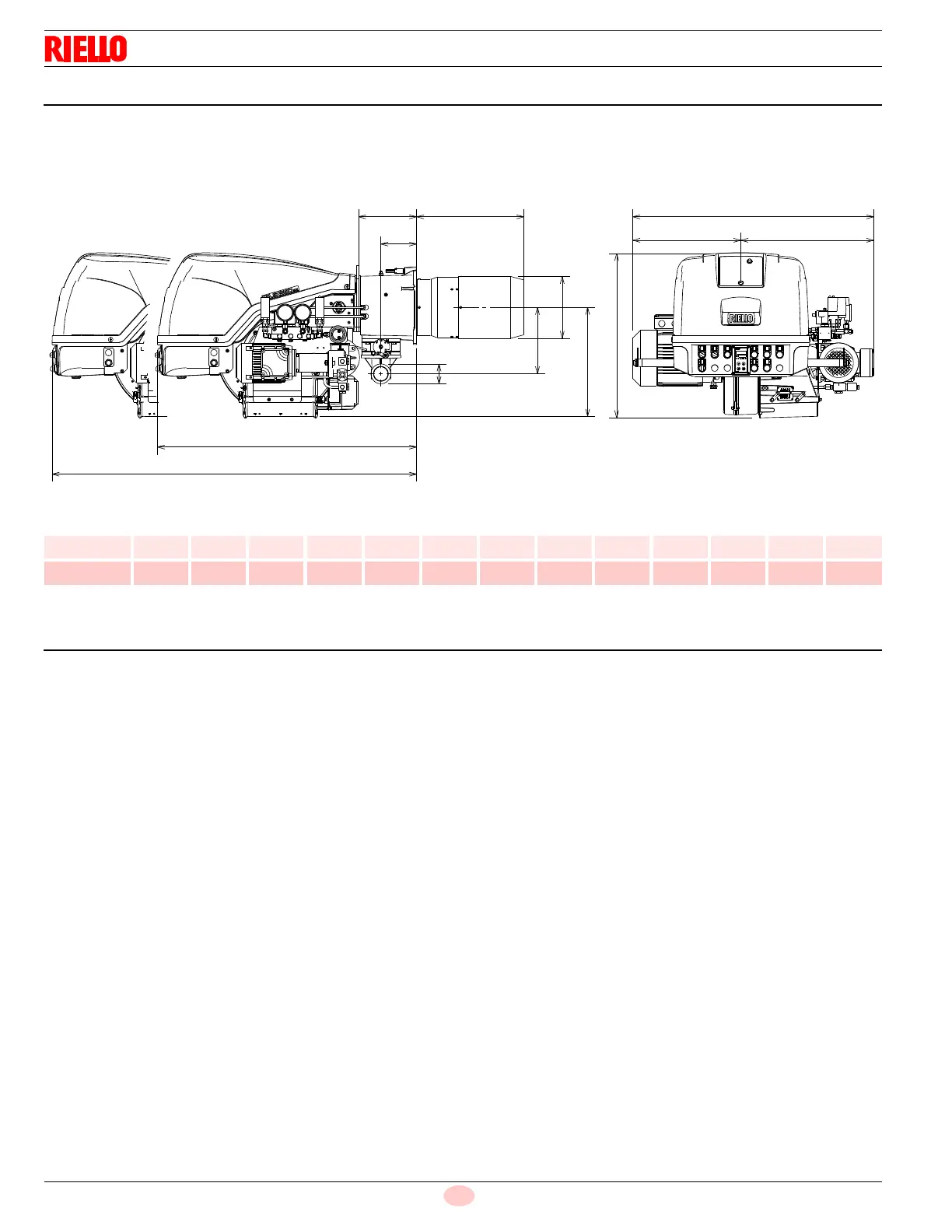
3.5 Burner dimensions
The maximum dimensions of the burners are given in Fig. 2.
Inspection of the combustion head requires the burner to be
opened and the rear part withdrawn on the slide bars.
The maximum dimension of the burner when open, without casing,
is give in measurement I.
Tab. F
3.6 Standard equipment
Gas train flange . . . . . . . . . . . . . . . . . . . . . . . . . . . . . . . . . . . No. 1
Flange fixing screws. . . . . . . . . . . . . . . . . . . . . . . . . . . . . . . . No. 4
Adaptor G 1/4” / 1/4” NPT . . . . . . . . . . . . . . . . . . . . . . . . . . . No. 1
Seal for gas train flange . . . . . . . . . . . . . . . . . . . . . . . . . . . . . No. 1
Connector for pilot line . . . . . . . . . . . . . . . . . . . . . . . . . . . . . . No. 1
Circular sector . . . . . . . . . . . . . . . . . . . . . . . . . . . . . . . . . . . . No. 4
Washer for screws . . . . . . . . . . . . . . . . . . . . . . . . . . . . . . . . . No. 4
Instruction booklet . . . . . . . . . . . . . . . . . . . . . . . . . . . . . . . . .No. 1
Model A B C D E F G H I L M N O
RLS 160/E 37
13
/
32“
16
49
/
64“
20
5
/
8“
25
1
/
2”
40
61
/
64“
14
39
/
64“
8
11
/
16“
17
5
/
32“
52
1
/
2”
8
45
/
64”
5
9
/
16”
10
5
/
16“
2”
RLS 200/E 37
13
/
32“
16
49
/
64“
20
5
/
8“
25
1
/
2”
40
61
/
64“
14
39
/
64“
8
11
/
16“
17
5
/
32“
52
1
/
2”
8
45
/
64”
5
9
/
16”
10
5
/
16“
2”