20095042
20
Installation
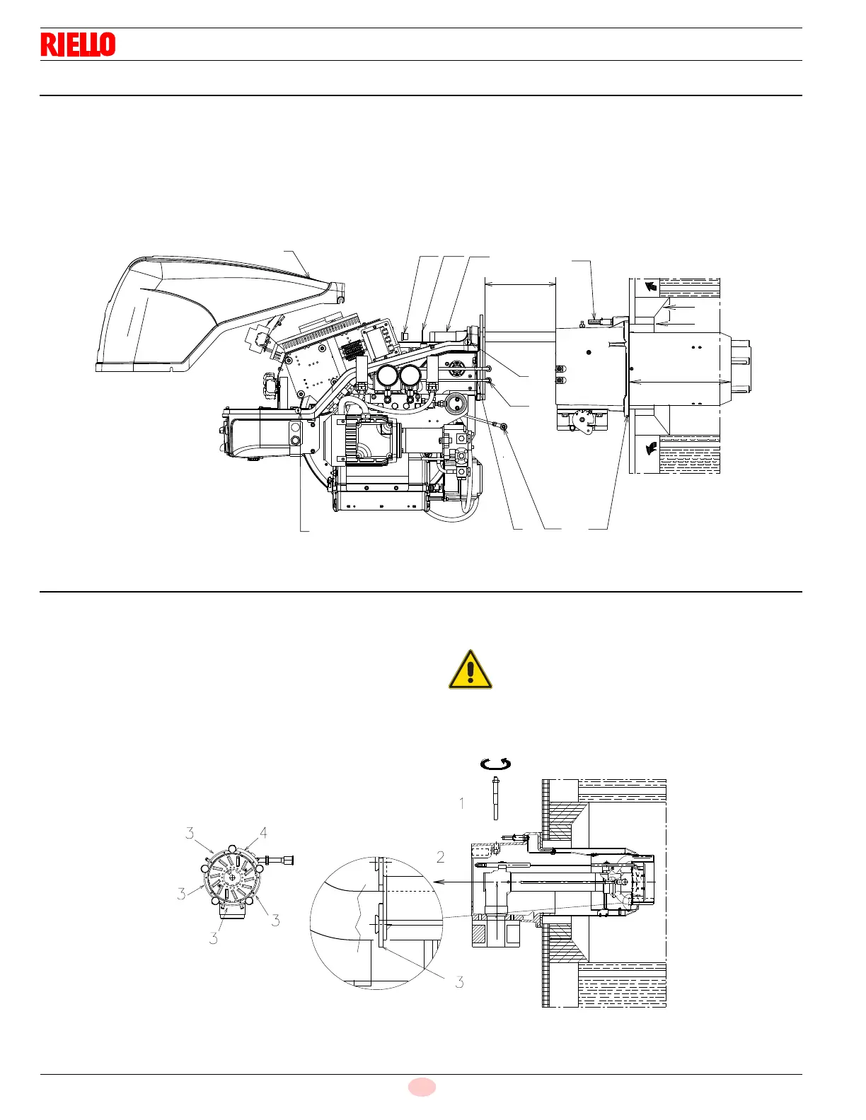
4.6 Securing the burner to the boiler
Detach the combustion head from the burner, (Fig. 12):
➤
disconnect the oil pipes by unscrewing the two connectors 6);
➤
loosen the 4 screws 3) and remove the cover 1);
➤
disengage the swivel coupling 14) from the graduated sector;
➤
remove the screws 2) from the slide bars 5);
➤
remove the 2 screws 4) and pull the burner back on slide bars
5) by about 4”;
➤
install the extension bars 31)(Fig. 6, page 12) and re-screw
the screws 2) including the safety plate 15);
➤
disconnect the electrode wires and then pull the burner com-
pletely off the slide bars.
4.7 Combustion head calibration
RLS 160/E (Fig. 13)
At this point check, whether the maximum delivery of the burner in
2nd stage operation is contained in area A) or in area B) of the firing
rate. See “Firing rates” on page 9.
If it is in area B) then no operation is required.
If, on the other hand, it is in area A), pre-set the combustion head
as below indicated:
➤
remove the screw 1)(Fig. 13) and extract the internal part 2);
➤
replace the 4 circular sectors 3) by unscrewing the relevant
screws, with the circular sectors supplied with the burner.
9
13
L
10
11
12
8
7
6
2 15
5
14
4
3
3
4"
1
Do not remove the circular sector 4.