20095042
12
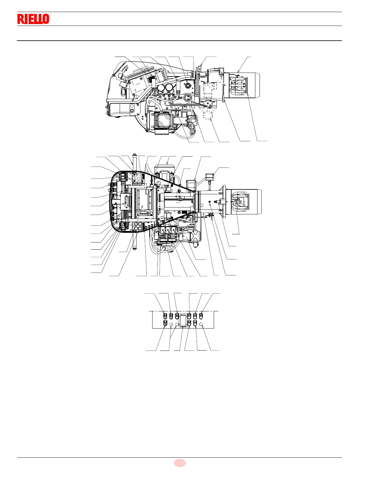
Technical description of the burner
3.10 Burner description
1 Combustion head
2 Ignition electrodes
3 Screw for combustion head adjustment
4 Sleeve
5 Fan motor
6 RWF55 modulator (with analog output 4-20 mA)
7 Fan motor contactor and thermal relay with reset button
8 UV scanner
9 Burner terminal strip “X1”
10 Holes for cables grommets for electrical wirings, accessories
and power supply (to be carried out by the installer)
11 Control box for checking flame and air/fuel ratio
12 Operator panel with LCD display
13 Flame inspection window
14 Low air pressure switch (differential operating type)
15 Slide bars for opening the burner and inspecting the combus-
tion head
16 Safety oil solenoid valve
17 Valve assembly with pressure regulator on nozzle return
18 Gas pressure test point and head fixing screw
19 Air pressure test point
20 Air servomotor
21 Pump motor
22 Low oil pressure switch
23 Pilot attachment
24 Pump
45
46
47
49
50
48
54 6
52
53
54
51
2328
13
3315
17
20
25
26
27
22
35
1
2
3
18
19
4
58
24
571634
55
21
11
10
44
42
40
43
59
12
9
38
37
36
10
56
31
7
55 5
30
32
8
29
55
39
41
14