20095042
28
Installation
4.14.1 Gas pressure
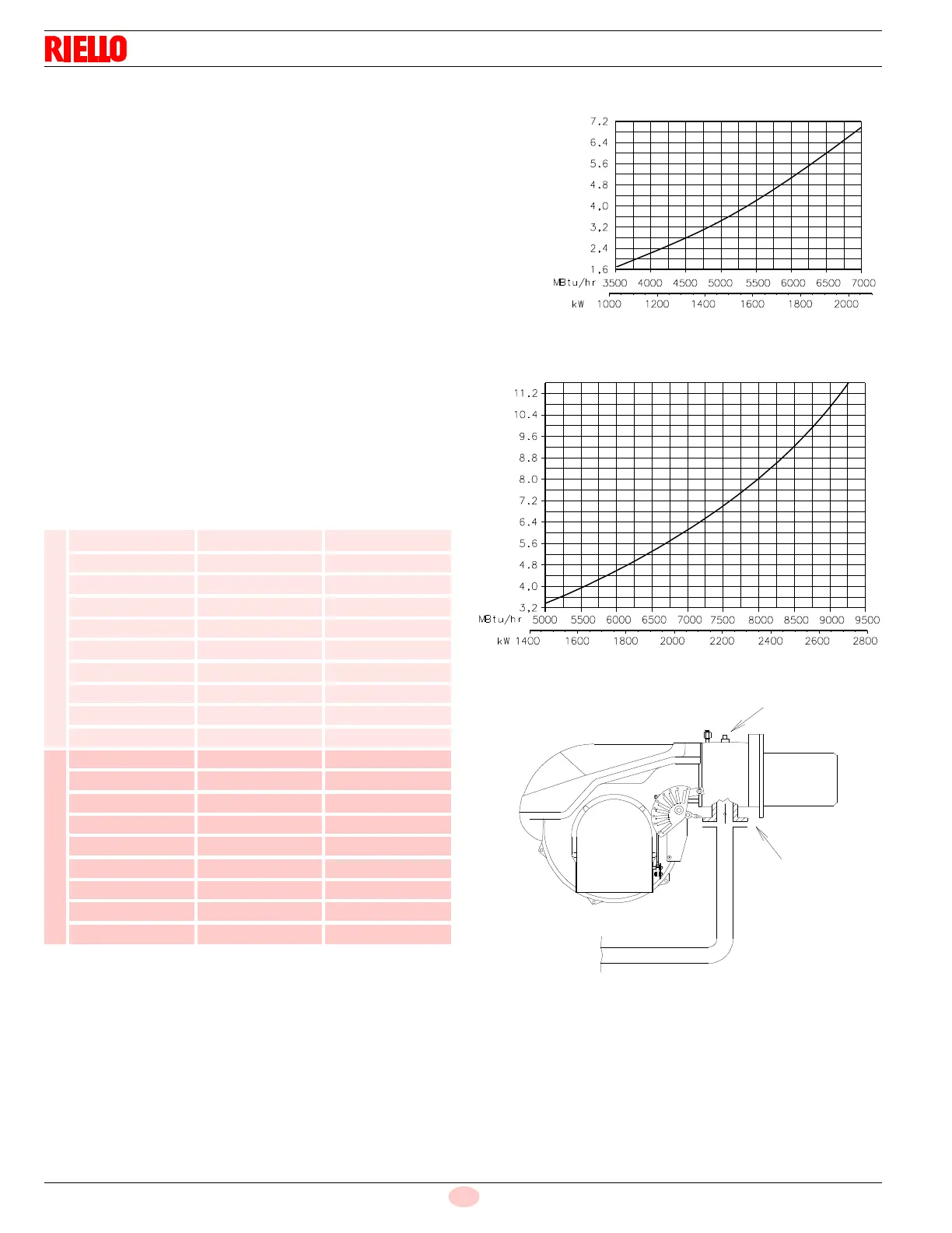
The adjacent diagrams are used to calculate manifold pressure
taking into account combustion chamber pressure.
Gas manifold pressure measured at test point 1)(Fig. 32), with:
• combustion chamber at 0” WC
• burner operating at maximum output
• Combustion head adjusted as indicated in diagram (Fig. 16)
Calculate the approximate high fire output of the burner as follows:
– subtract the combustion chamber pressure from the gas pres-
sure measured at test point 1)(Fig. 32).
– Find the nearest pressure value to your result in Fig. 31.
– Read off the corresponding output on the left.
Example for RLS 200/EV
• Maximum output operation
• Natural gas
• Gas pressure at test point 1)(Fig. 32) = 9.2” WC
• Pressure in combustion chamber = 1.2” WC
9.2 - 1.2 = 8” WC
A maximum output of 8.000 MBtu/hr shown in diagram corre-
sponds to 8” WC pressure.
This value serves as a rough guide, the effective delivery must be
measured at the gas meter.
Tab. M
* The values are referred to the butterfly gas valve.
kW MBtu/hr
∆
p (“WC)*
RLS 160/E
930 3175 0.35
996 3400 0.39
1099 3750 0.50
1202 4100 0.63
1400 4780 0.86
1500 5120 1.00
1600 5460 1.15
1700 5800 1.30
1861 6350 1.50
2051 7000 1.65
RLS 200/E
1400 4775 1.2
1500 5120 1.4
1600 5460 1.6
1700 5800 1.8
1800 6140 2.0
1900 6480 2.3
2000 6874 2.5
2150 7560 3.0
2460 8393 3.8
Fig. 31
Burner output
D9127
∆p [“WC]
∆p [“WC]
Burner output
D3188
RLS 160/E
RLS 200/E