Technical description of the burner
11
20106891
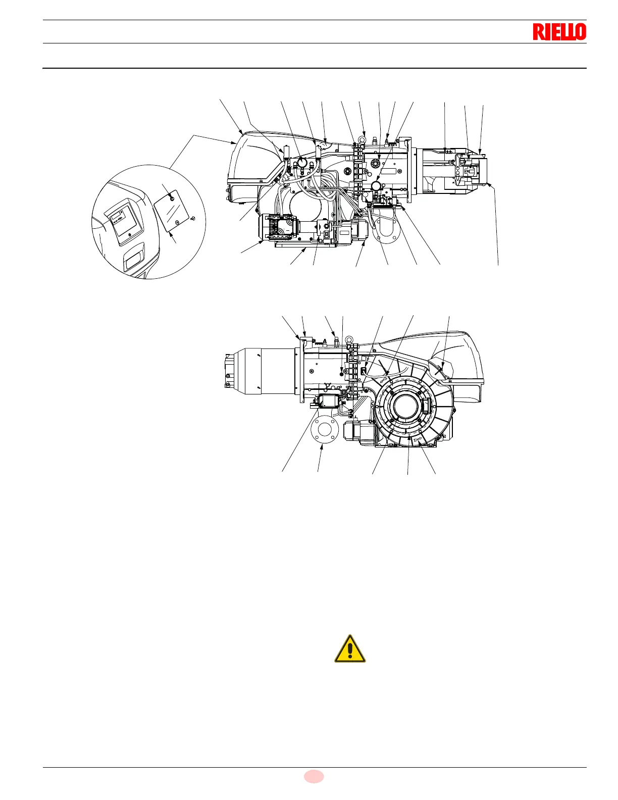
3.7 Burner description
1 Lifting eyebolts
2Fan
3Fan motor
4 Air gate valve servomotor
5 Gas pressure test point
6 Combustion head
7 Ignition pilot
8 Flame stability disk
9 Electric panel board - cover
10 Hinge for opening burner
11 Air inlet to fan
12 Manifold
13 Thermal insulation screen for securing burner to boiler
14 Gas train flange
15 Shutter
16 Flame inspection window
17 Gas butterfly valve
18 Combustion head air pressure test point
19 Air pressure test point “+”
20 Max gas pressure switch with pressure test point
21 Flame detector
22 Indication for checking the fan motor rotation
23 Oil modulator and gas butterfly valve servomotor
24 Pump
25 Pump motor
26 Valve group (see Fig. 4 on page 12)
27 Minimum oil pressure switch
28 Nozzle delivery pressure gauge
29 Nozzle return pressure gauge
30 Oil modulator
31 Maximum oil pressure switch
32 Reset button
33 Transparent protection
34 Pilot gas train attachment
2
1213 1921
23
3
18
14
22
16
22
34
26
25
11
24
4
20
30
17
6
7
15
29
5
1
10
1
28
9
27
8
32
33
31
The burner can be opened either on the right or left
sides, irrespective of the side from which fuel is sup-
plied. When the burner is closed, the hinge can be
re-positioned on the opposite side.