20106891
20
Installation
4.5 Preparing the boiler
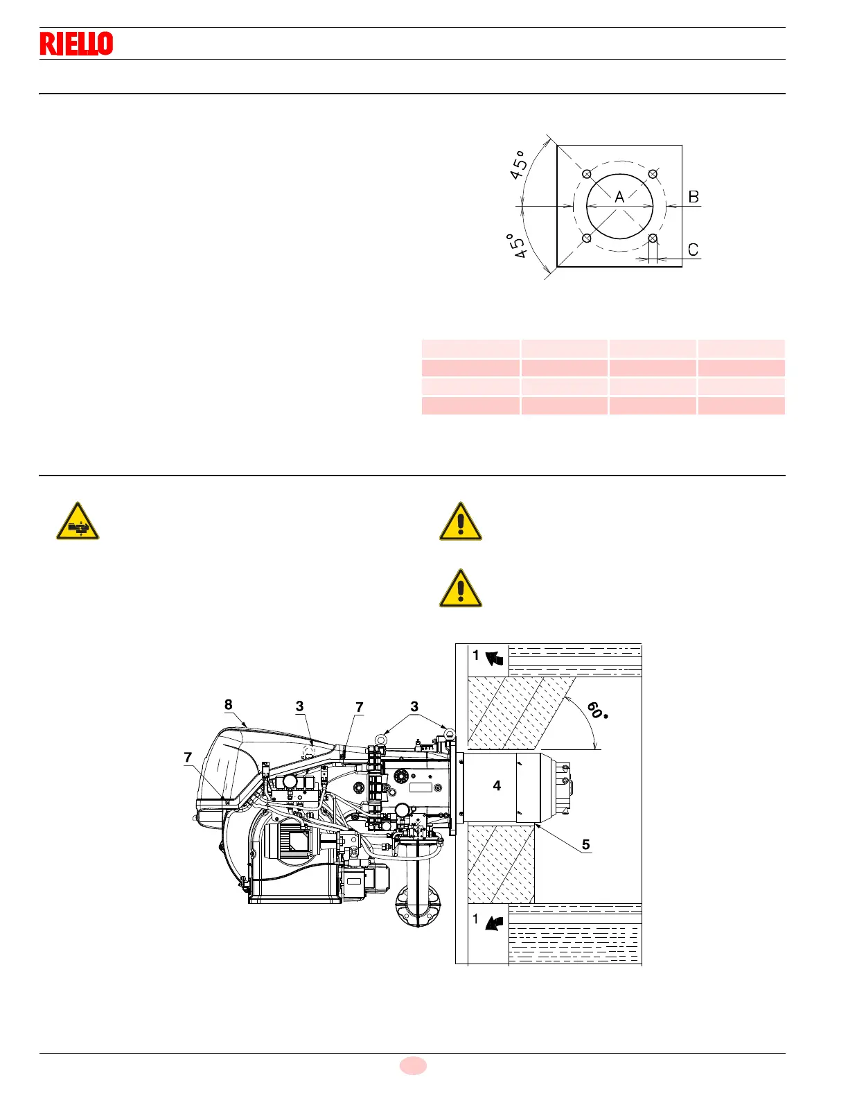
4.5.1 Boring the boiler plate
Drill the combustion chamber locking plate as shown in Fig. 11.
The position of the threaded holes can be marked using the ther-
mal screen supplied with the burner.
4.5.2 Blast tube length
The length of the blast tube must be selected according to the indi-
cations provided by the manufacturer of the boiler, and in any case
it must be greater than the thickness of the boiler door complete
with its fettling.
For boilers with front flue passes 1)(Fig. 18 on page 23) or flame in-
version chamber, a protection in refractory material 5) must be in-
serted between the boiler fettling 2) and the blast tube 4).
The refractory can have a conical shape (minimum 60°).
This protective fettling must not compromise the extraction of the
blast tube.
For boilers with a water-cooled front piece, a refractory lining 2)-
5)(Fig. 18 on page 23) is not necessary, unless expressly request-
ed by the boiler manufacturer.
Tab. K
4.6 Securing the burner to the boiler
Fit the heat insulation supplied onto the blast tube (4)(Fig. 12).
Fit the entire burner onto the boiler hole prepared previously,
and fasten with the screws supplied.
inch ABC
RLS 280/E 13
1
/
4”
17
13
/
16”
3
/
4”
coarse
RLS 310/E 13
1
/
4”
17
13
/
16”
3
/
4”
coarse
RLS 410/E 13
1
/
4”
17
13
/
16”
3
/
4”
coarse
RLS 510/E 13
1
/
4”
17
13
/
16”
3
/
4”
coarse
Prepare a suitable lifting system using the rings
3)(Fig. 12), after removing the fixing screws 7) of the
casing 8).
The seal between burner and boiler must be air-
tight.
The manufacturer declines any and every re-
sponsibility for any possible lifting movements,
different from those indicated in this manual.