20106891
28
Installation
4.13 Hydraulic connections
The pumps are equipped with a by-pass that connects return
line and suction line.
The pumps are installed on the burner with the by-pass closed
by screw 6)(Fig. 21). It is therefore necessary to connect both
hoses to the pump.
Remove the plugs from the suction and return connections of
the pump.
Insert the hose connections with the supplied seals into the
connections and screw them down.
Install the hoses where they cannot be stepped on or come
into contact with hot surfaces of the boiler and where they do
not hamper the opening of the burner.
Now connect the other end of the hoses to the suction and
return lines by using the supplied nipples.
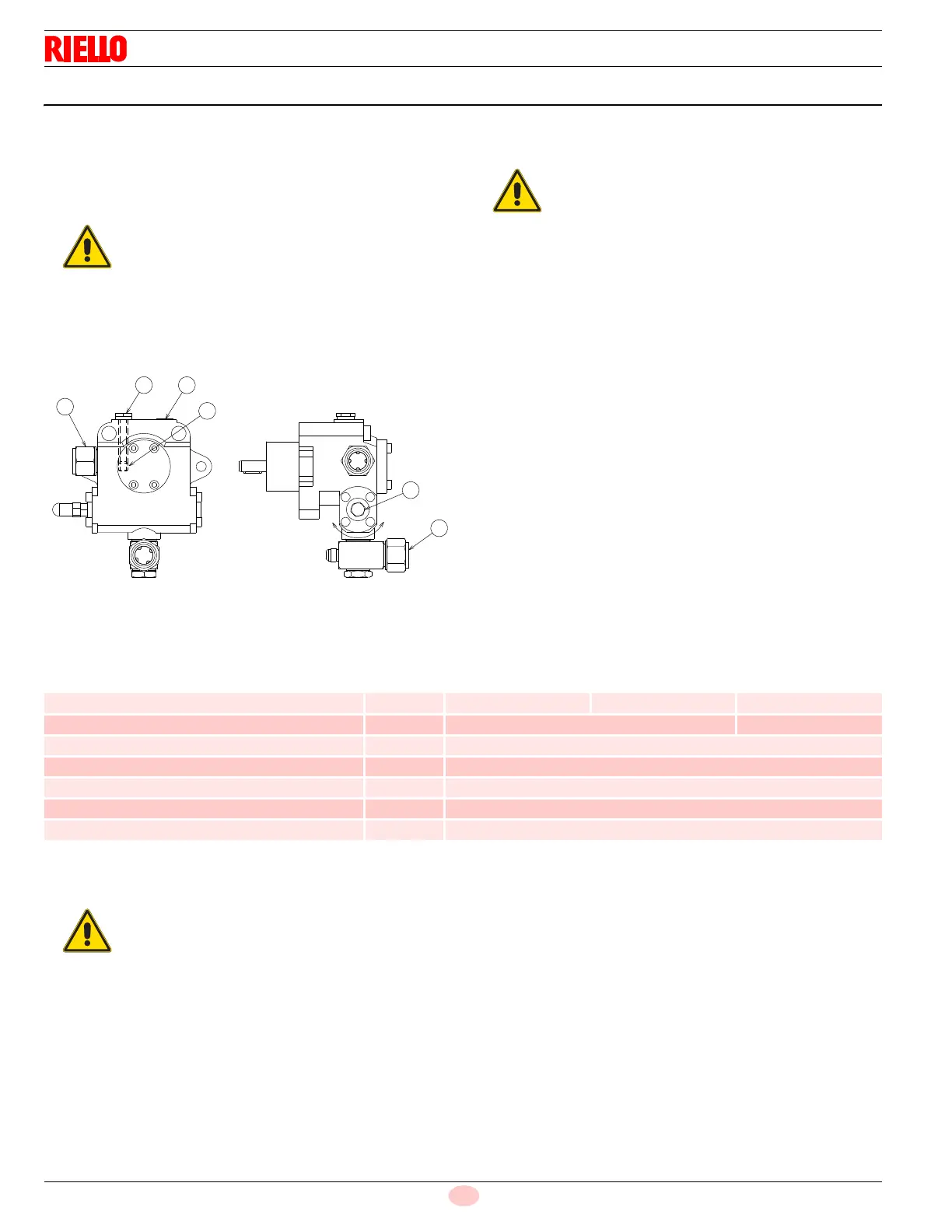
4.13.1 Pump
Key (Fig. 21)
1 Suction line G 3/4” NPT
2 Return line G 3/4” NPT
3 Vacuometer connection G 1/4”
4 Pressure adjuster
5 By-pass screws
6 Gauge connection G 1/4”
Technical data
Tab. N
Priming pump
In order for the pump (Fig. 21) to self-prime, it is vital that the
screw 4) of the pump be loosened to vent the air contained in
the suction line.
Start the burner by closing the remote controls.
As soon as the burner starts, check the direction of rotation of
the fan blade.
The pump can be considered to be primed when the light oil
starts coming out of the screw 4). Close the burner and undo
the screws 4).
The time required for this operation depends upon the diameter
and length of the suction tubing.
If the pump fails to prime at first start-up and the burner locks out,
wait approx. 15 seconds, reset the burner, and then repeat the
start-up operation.
And so on. After 5 or 6 starting operations allow 2 or 3 minutes for
the transformer to cool.
Do not light the flame sensor or the burner will lock out; the burner
should lock out anyway about 10 seconds after it starts.
The pump will break immediately if it is run with
the return line closed and the by-pass screw in-
serted.
Take care that the hoses are not stretched or twist-
ed during installation.
Pump model
TA3
(RLS 280-310/E)
TA4
(RLS 410/E)
TA5
(RLS 510/E)
Min. delivery rate at 300 PSI pressure GPH 218 290 403
Delivery pressure range PSI 102 - 580 102 - 435
Max. suction pressure PSI 7.0
Viscosity range cSt 3 - 75
Max. oil temperature °F 302 (150 °C)
Max. return pressure PSI 73.0
Pressure calibration in the factory PSI 300
Before starting the burner, make sure that the tank
return line is not clogged.
Obstructions in the line could cause the sealing or-
gan located on the pump shaft to break.