Installation
23
20106891
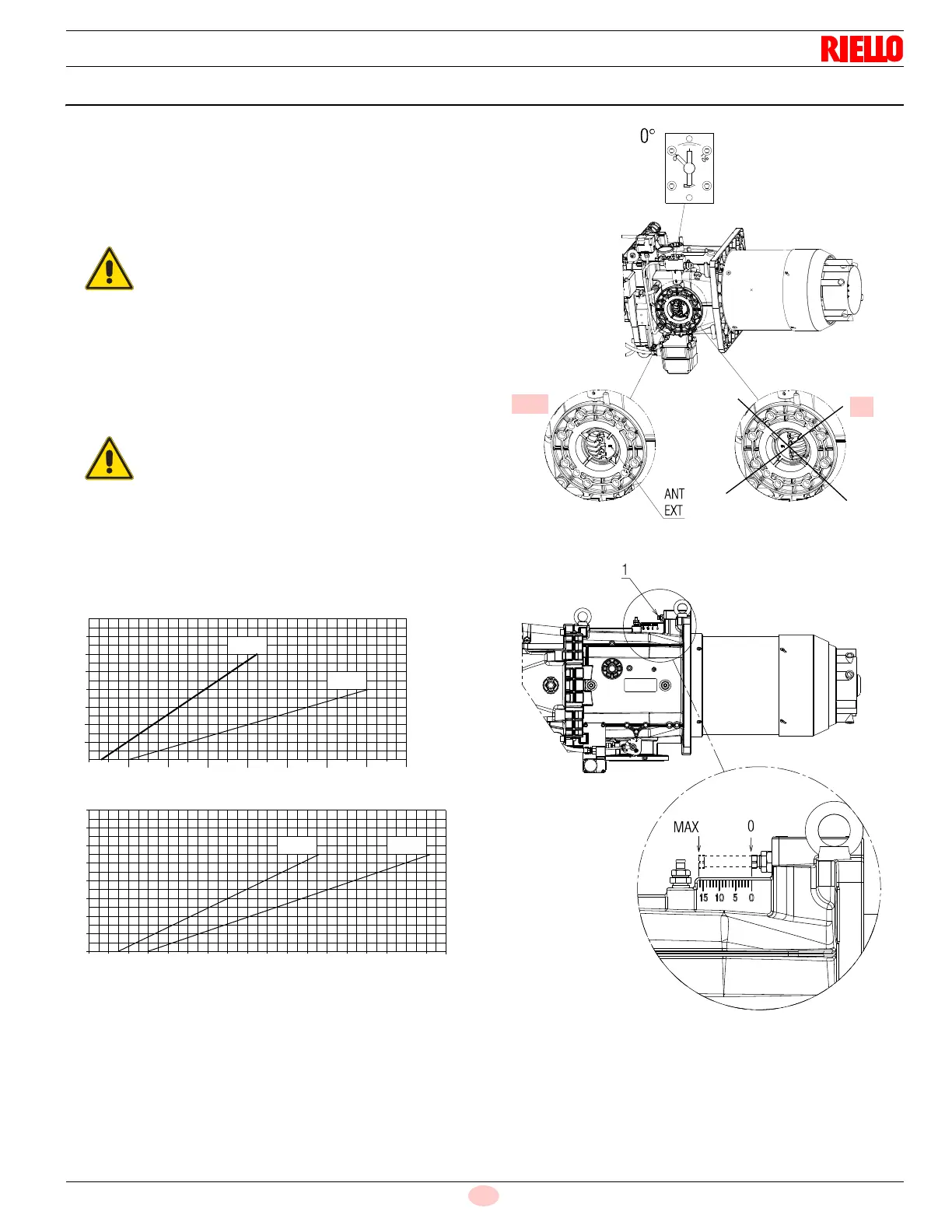
4.10 Combustion head setting
Rotate the screw 1) until the notch you have found corresponds
with the front surface of the screw itself.
The combustion head is opened by turning the screw 1) anticlock-
wise.
The combustion head is closed by turning the screw 1) clockwise
(Fig. 18).
Before starting the burner, carry out the adjustments for the output
required.
Depending on the specific application, the adjustment can be
modified.
The burner leaves the factory with the combustion
head adjusted to notch 0 (Fig. 18).
This adjustment allows you to secure the moving
parts when the burner is being transported.
The combustion head can be adjusted within the fol-
lowing fields:
RLS 280/E: 0 - 12;
RLS 310/E: 0 - 11;
RLS 410/E: 0 - 8;
RLS 510/E: 0 - 11.
No adjustment can be made outside these intervals.
10
12
12000
14000
16000
18000
20000
16
14
1200010000800060004000
2000
14000
16000
18000
RLS 410
RLS 280
RLS 310
RLS 510
Fig. 16
20126486
No. Notches
MBtu/hr