Technical description of the burner
17
20106891
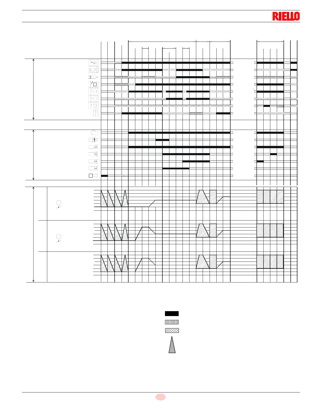
Operation sequence of the burner
Legend to the sequence diagrams:
Valve proving takes place depending on the parameter:
2) Only with valve proving on start-up
3) Parameter: with/without alarm in the event of start prevention
4) In the event of an erroneous signal on start-up, followed by
phase 10, otherwise phase 70
0° Position as supplied (0°)
90° Actuator fully open (90°)
Assignment of times:
t1 Pre-purge time
TSA1 Safety time 1 gas / oil
TSA2 Safety time 2 gas / oil
00 02 12 22 24 30 36 38 40 42 44 50 52 60 62
70 72 74
81 82 8380
3)
4)
2)
TSA1
TSA2
t1
90
p
a
T
P
P
T
P
10
Shutdown
Operation
Startup Valve proving
OUTPUTS
INPUTS
Phase number
Fuel
Actuator 2
Air
Actuator 1
Actuators
Safety limit thermostat (STB)
Control thermostat or pressurestat (R)
Flame signal (FS)
Air pressure switch (LP)
Pressure switch-min (Pmin)
Pressure switch-max (Pmax)
Valve proving / leakage test (P LT)
POC (alternative to Pmax)
No-load position
Ignition load
Postpurge position
Nominal load
Low-fire
90°
0°
VSD
Motor (M)
Ignition transformer
(Z)
Alarm (AL)
Safety valve (SV)
Fuel valve 1 (V1)
Fuel valve 2 (V2)
Pilot valve (PV)
No-load position
Ignition load
Postpurge position
Nominal load
Low-fire
90°
0°
No-load position
Ignition load
Postpurge position
Nominal load
Low-fire
90°
0°
Signal ON
Signal OFF
Any signal is allowed
In standby: after referencing, the actuator is driven to the
no-load position