25
20068446
Installation
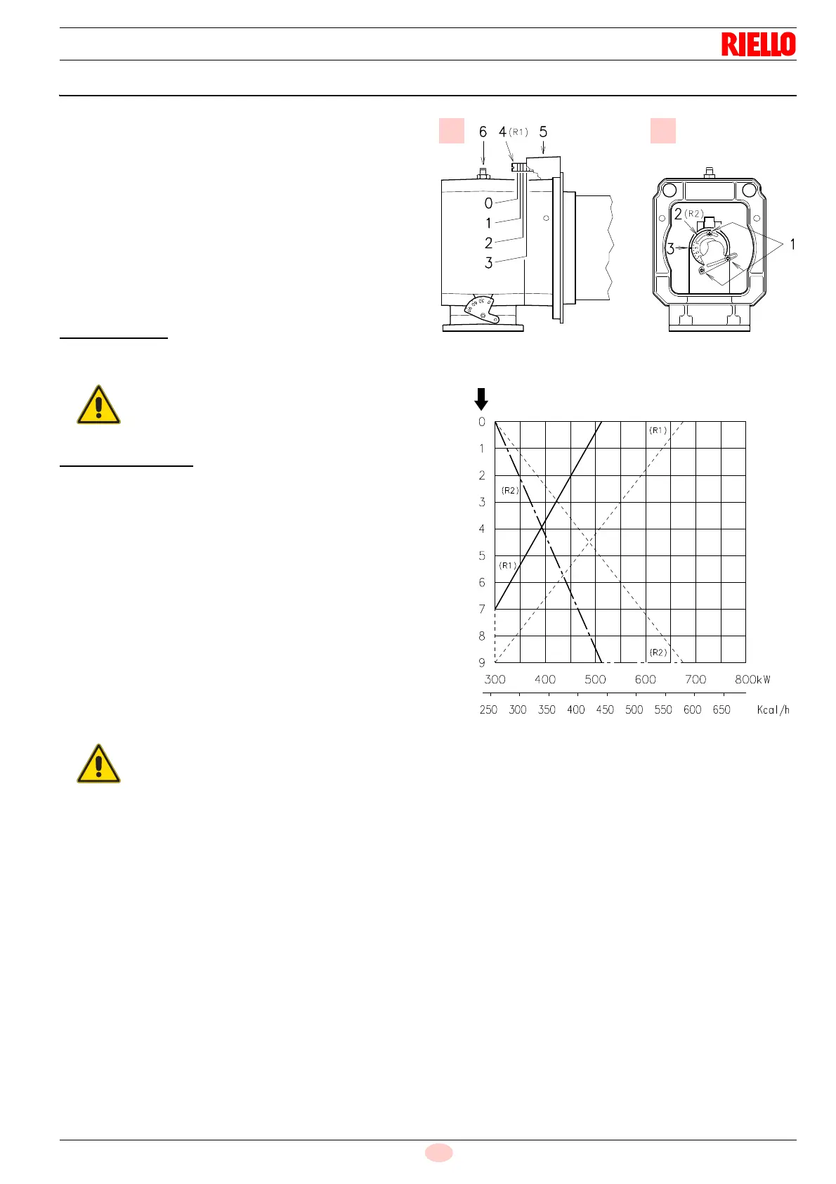
5.8 Combustion head adjustment
At this stage of installation the blast tube and the pipe coupling
are secured to the boiler as shown in A)(Fig. 18).
Therefore the adjustment of the combustion head is particularly
easy, an adjustment that depends solely on the maximum power
of the burner.
Therefore, this value must be set before adjusting the combus-
tion head.
Two adjustments of the head are foreseen:
– air R1 A)(Fig. 18)
– gas/air R2 B)(Fig. 18)
In the diagram (Fig. 19) find the notch at which both the air and
gas should be adjusted.
Air adjustment R1
Rotate the screw 4)(Fig. 18) until the notch you have found
corresponds with the front surface 5)(Fig. 18) of the flange.
Gas/air adjustment R2
Loosen the 3 screws 1)(Fig. 18) and rotate the ring nut 2)
until the notch you have found corresponds with the
index 3).
Block the 3 screws 1).
Example:
Burner output = 450 kW
The diagram (Fig. 19) shows that the adjustments are as follows
for this output:
– air R1 = notch 2
– gas/air R2 = notch 6
The diagram (Fig. 19) indicates the optimum adjustment for a
type of boiler according to Fig. 4 at page 12.
If the gas pressure allows it, by closing the ring nut 2)(Fig. 18) you
obtain reductions in the formation of NOx.
To facilitate the adjustment, loosen the screw 6)
(Fig. 18), adjust, then block.
If the pressure in the combustion chamber is
equal to 0 mbar, the adjustments of the air and the
gas/air must be made with reference to the dotted
line on the diagrams.
Fig. 19
No. of notches (air = gas)
D11604
Max burner output