20068446
34
Start-up, calibration and operation of the burner
6.5 Final calibration of the pressure switches
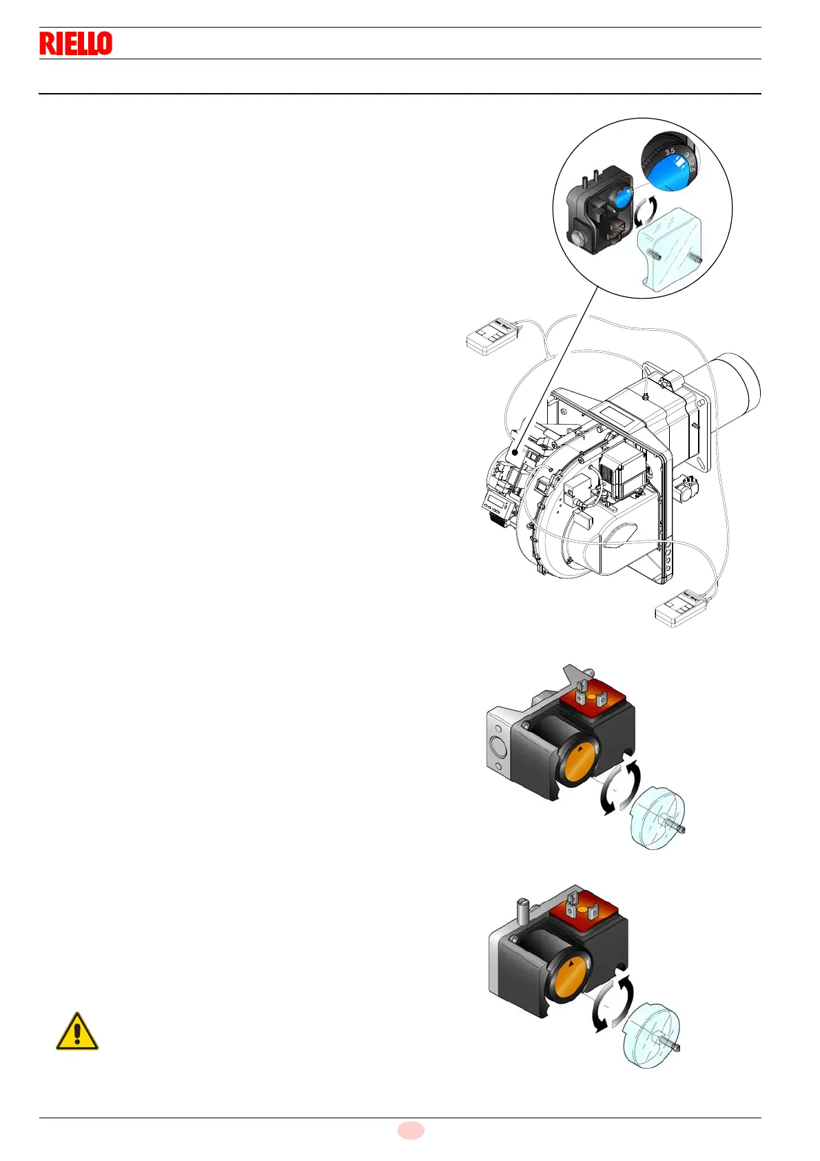
6.5.1 Air pressure switch
Adjust the air pressure switch (Fig. 32) after having performed all
other burner adjustments with the air pressure switch set to the
start of the scale.
With the burner working at MIN output, insert a combustion
analyser in the stack, slowly close the suction inlet of the fan (for
example, with a piece of cardboard) until the CO value does not
exceed 100 ppm.
Slowly turn the appropriate knob clockwise until the burner goes
into lockout.
Check the indication of the arrow pointing upwards on the gradu-
ated scale. Turn the knob clockwise again, until the value shown
on the graduated scale corresponds with the arrow pointing
downwards, and so recovering the hysteresis of the pressure
switch (shown by the white mark on a blue background, between
the two arrows).
Now check the correct start-up of the burner. If the burner locks
out again, turn the knob slightly anticlockwise. During these op-
erations it may be useful to measure the air pressure with a pres-
sure gauge.
The connection of the pressure gauge is shown in Fig. 32.
The standard configuration is that with the air pressure switch
connected in absolute mode. Note the presence of a “T” connec-
tion, not supplied.
In certain applications in strong depression situations, the con-
nection of the pressure switch does not allow it to change over.
In this case it is necessary to connect the pressure switch in dif-
ferential mode, applying a second tube between the air pressure
switch and the fan suction line mouth.
In this case also, the pressure gauge must be connected in differ-
ential mode, as shown in Fig. 32.
6.5.2 Maximum gas pressure switch
Adjust the maximum gas pressure switch (Fig. 33) after having
performed all other burner adjustments with the maximum gas
pressure switch set to the end of the scale.
With the burner operating at maximum output, lower adjustment
pressure by slowly turning the relative knob anticlockwise until
the burner locks out.
Turn the knob clockwise by 0,2 kPa (2 mbar) and repeat the start-
up of the burner.
If the burner locks out again, turn the knob clockwise again by 0,1
kPa (1 mbar).
6.5.3 Minimum gas pressure switch
Adjust the minimum gas pressure switch (Fig. 34) after having
performed all other burner adjustments with the pressure switch
set to the start of the scale.
With the burner operating at maximum output, increase adjust-
ment pressure by slowly turning the relative knob clockwise until
the burner locks out.
Then turn the knob anticlockwise by 0,2 kPa (2 mbar) and repeat
the burner start-up to ensure it is regular.
If the burner locks out again, turn the knob anticlockwise again by
0,1 kPa (1 mbar).
1 kPa = 10 mbar
+
Fig. 32
D3951
Connecting the pressure gauge with
the pressure switch in differential mode
Connecting the pressure
gauge with the pressure switch
in absolute mode
D8153