3
22
3
33
4
5
3
8
10
15
10
13
14
12
1
EAF
EAF
15
6
33
33
11
6
7
17 5
33
3
5
3
4
3
5
3
4
b The choice of system components and the method
of their installation are left up to the heating engineer
installing the system. Installers must use their exper-
tise to ensure proper installation and functioning in
compliance with all applicable legislation.
b Circuits filled with anti-freeze must be fitted with
water disconnectors.
b If needed, water supplies and recovery circuits must
be conditioned by suitable treatment systems. See
the table alongside for reference values.
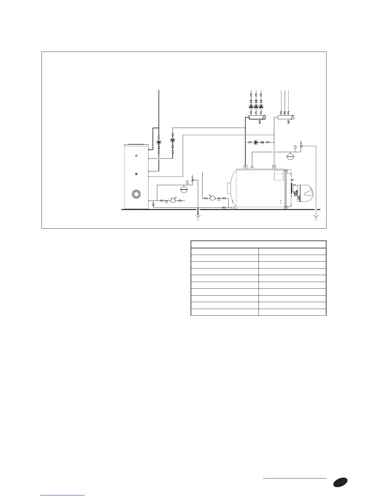
Schematic diagram - central heating and domestic hot water production RTQ
115÷2400 3S
REFERENCE VALUES
PH 6-8
Electrical conductivity below 200 μS/cm (25°C)
Chlorine ions below 50 ppm
Sulphuric acid ions below 50 ppm
Total iron below 0,3 ppm
Alkalinity M below 50 ppm
Total hardness 35° F
Sulphur ions none
Ammonia ions none
Silicon ions below 30 ppm
1 - Boiler
2 - Central heating manifolds
3 - Disconnect valves
4 - System pumps
5 - Non-return valves
6 - Automatic vent valve
7 - Boiler safety valve
8 - Boiler drain cock
9 - Storage cylinder safety valve
10 - System filling cock
11 - CH expansion vessel
12 -
r
7200 storage cylinder
13 - Storage cylinder drain cock
14 - DHW expansion vessel
15 - Softener filter
16 - Pressure reducer
17 - Anti-condensate pump
DRAINS DRAINS
HEATING
FLOW
HEATING
RETURN
DHW USER
POINTS