RIGOL Chapter 2 Constant Voltage Tests
DP800 Performance Verification Manual
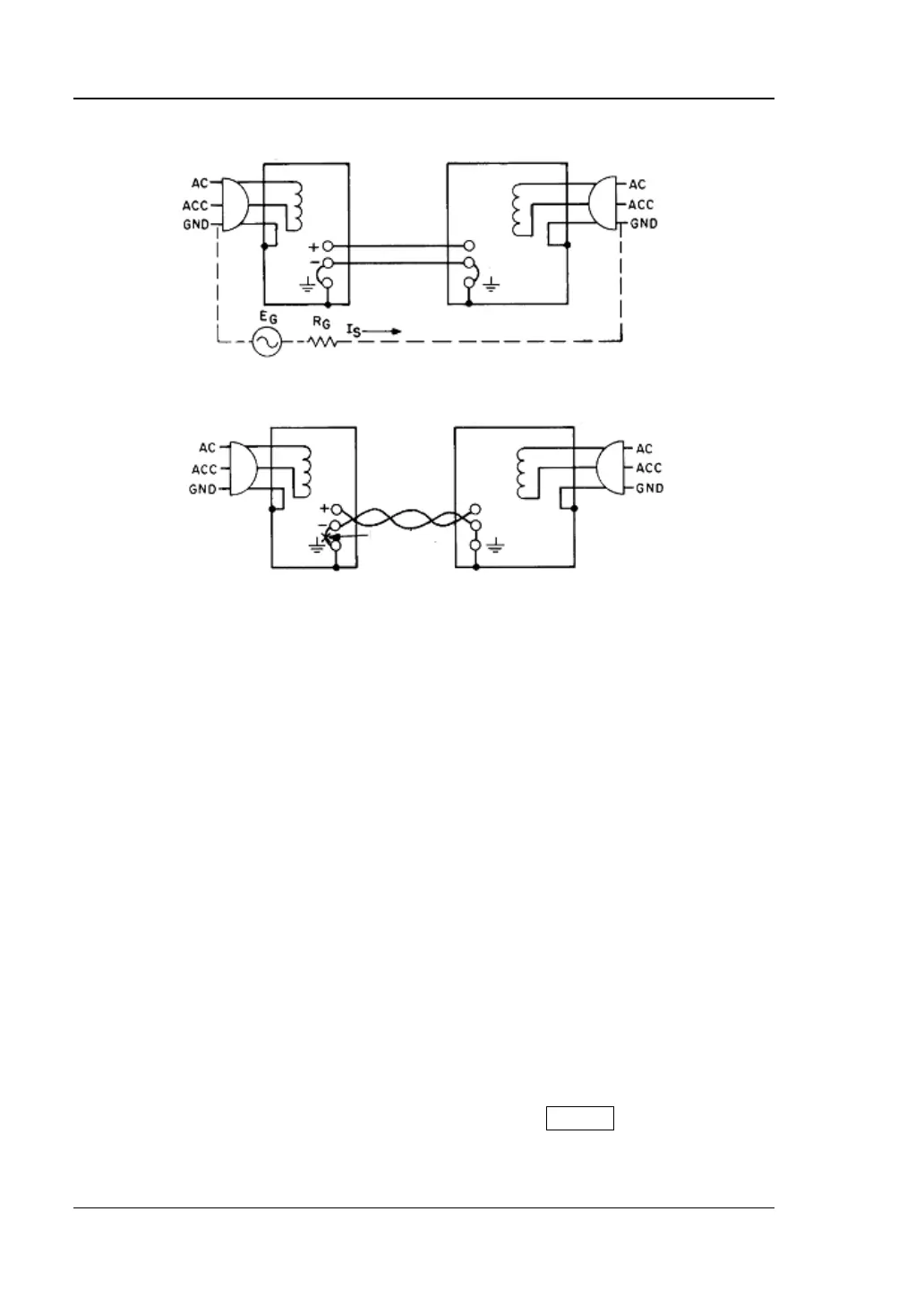
A. Incorrect Connection
B. Correct Connection
Figure 2-3 Peak-peak Value Measurement Connections
Please use resistive load instead of electronic load to avoid the effect on the
noise measurement of the power supply caused by the electronic load noise.
Please refer to Table 2-12 for the resistance of the resistive load.
Connect the positive terminal of the oscilloscope probe to the positive
terminal (+) of the output terminals of the channel under test of the power
supply and connect the ground terminal of the oscilloscope probe to the
negative terminal (-) of the output terminals of the channel under test of the
power supply. During the test, please ensure the effective contact. Note that
you are recommended to use ground spring as ground wire so as to
minimize the current coupling area between the probe tip and the ground
wire and to minimize the space radiation interference.
2. Turn on the AC power supply; set its voltage to 230V and frequency to 50Hz.
Note: The voltage setting of the AC power supply in this step should be in
accordance with the value selected by the voltage selector at the rear panel of
DP800.
3. Turn on DP800 and press the channel selecting key at the front panel to select
CH1 as the channel to be tested. Set the voltage and current of the channel
under test according to Table 2-12
. Then, press the On/Off key corresponding
to the channel under test to enable the output of the channel.
 Loading...