Chapter 2 Constant Voltage Tests RIGOL
DP800 Performance Verification Manual
3. Turn on DP800 and press the channel selecting key at the front panel to select
CH1 as the channel to be tested. Set the voltage and current of the channel
under test according to Table 2-17
. Then, press the On/Off key corresponding
to the channel under test to enable the output of the channel.
4. Turn on the electronic load and set the electronic load parameters. Select the CC
dynamic response mode (CCDH mode); set CCDH1 to the rated current value of
the channel (range) under test, CCDH2 to the current value of the channel
(range) under test with
half load (for the CCDH1 and CCDH2 values, please refer
to Table 2-17), CCDHT1 and CCDHT2 to 500μs (namely 1kHz frequency and
50% duty cycle), the rising edge time and falling edge time to 250mA/μs. Turn
on the electronic load and make sure that the programmable electronic load is in
CC mode.
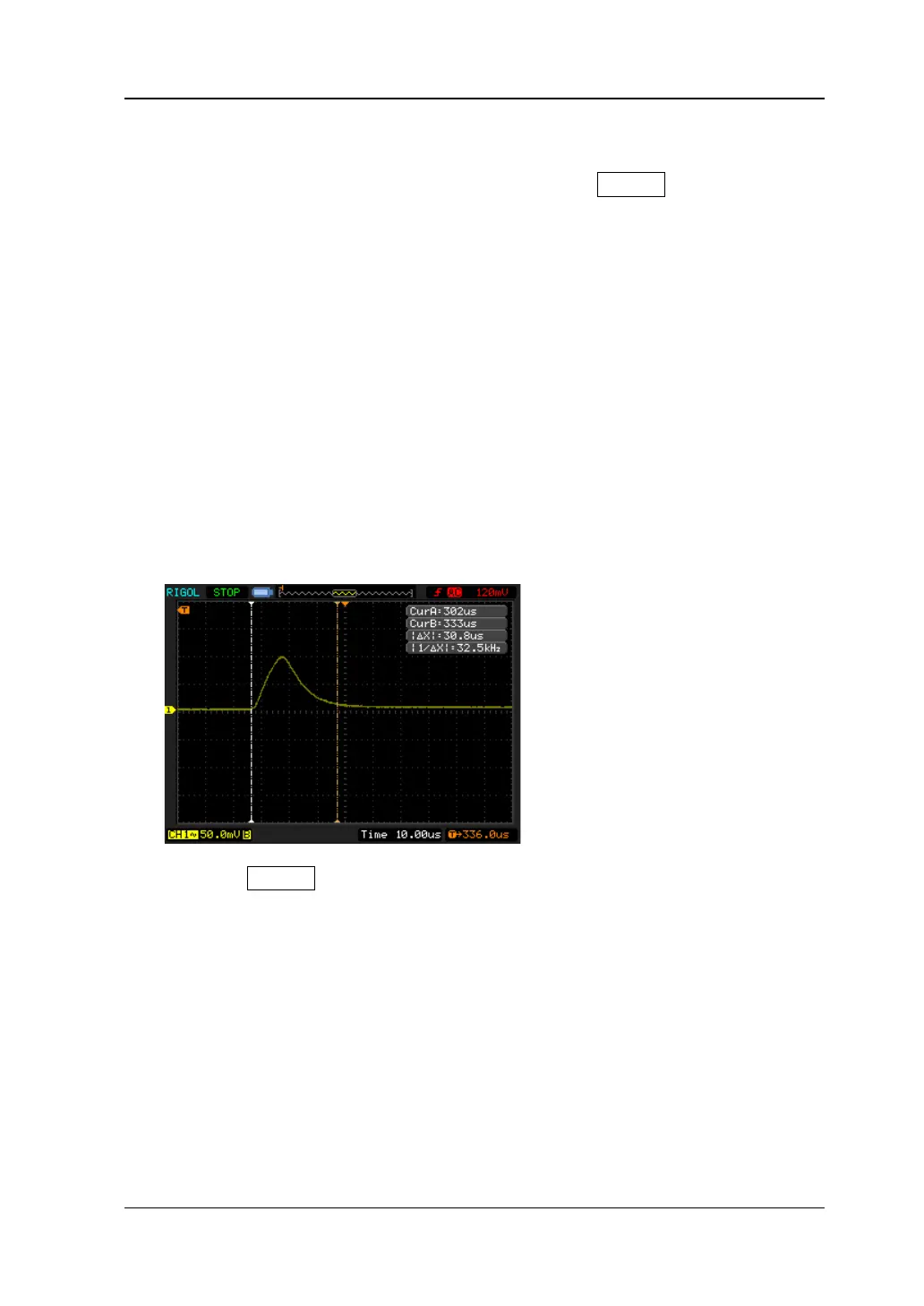
5. Turn on the oscilloscope and set the oscilloscope parameters. Set the coupling
mode to AC, the trigger source to AC Line and enable the 20MHz bandwidth limit.
Enable the cursor measurement function and measure the transient response
time (namely ΔX) displayed on the screen of the oscilloscope, as shown in the
figure below, and compare it with the specified specification in Table 2-17.
6. Press the On/Off key corresponding to the channel under test at the front
channel to disable the output of the channel under test.
7. Repeat steps 1 to 6 to test the transient response time of CH2 and CH3 until
finishing the transient response time tests of all channels.