Chapter 3 Constant Current Tests RIGOL
DP800 Performance Verification Manual
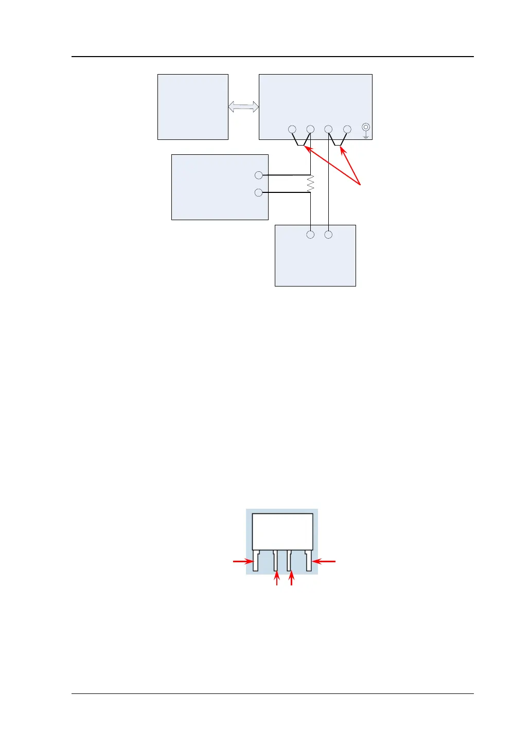
DP800
Electronic Load/
Resistive Load
AC Power
Supply
Multimeter/
Oscilloscope/
RMS Voltmeter
+
-
-
+
S+ + - S-
+
-
R
M
+
-
Figure 3-2 CC Test Connections (Sense)
Notes:
During the CC tests, make connections according to Figure 3-1 for the normal
channels (namely the channels that do not support the Sense function) of the
DP800 series power supply. For the channels that support the Sense function
(CH2 of DP821A and DP811A), make connections according to Figure 3-2 (note
to short-circuit the (S+) and (+) terminals, (S-) and (-) terminals of the channel
respectively) and turn on the Sense function of the channel during the test
process to measure the specifications under Sense mode.
The R
M
in the figures above is a 4-wire current sampling resistor (please select
current sampling resistor with suitable resistance according to the test item and
the channel to be tested). As shown in Figure 3-3, C represents the current
measurement terminal and S represents the voltage measurement terminal.
During the test, please make the correct connections.
S S
Figure 3-3 4-wire Current Sampling Resistor
 Loading...