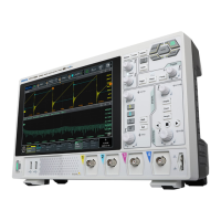
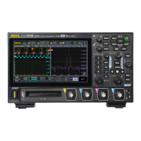
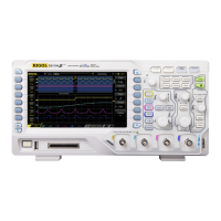
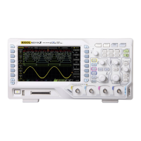
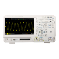
Do you have a question about the Rigol HDO1074 and is the answer not in the manual?
Precautions to avoid personal injury or damage to the instrument and connected products.
Explains warning, danger, caution symbols and terms used in the manual.
Covers tilting, connecting power, turn-on, fuse replacement, language, and probes.
Covers enabling/disabling channels, adjusting scale, offset, and coupling modes.
Manually sets probe attenuation and corrects channel-to-channel skew.
Sets the time per division for horizontal waveform display.
Explains Normal, Average, Peak, High Res, and UltraAcquire data capture modes.
Selects the signal source and sets the trigger voltage level.
Explains the operation of Auto, Normal, and Single trigger modes.
Covers Edge, Pulse Width, Slope, Video, Pattern, Duration, Timeout, Runt, Window, Delay, Setup/Hold, Nth Edge, RS232, I2C, SPI, CAN, LIN triggers.
Performs mathematical operations like addition, subtraction, integration, differentiation, and FFT.
Using cursors to measure X and Y axis values on waveforms.
Describes enabling, setting limits, and removing DVM measurements.
Explains enabling, setting resolution, and clearing counter measurements.
Enables test, selects source, creates masks, and configures output events.
Starts/stops tests and displays pass/fail statistics.
Configures clock, bus settings, display format, and event table for parallel data.
Configures source, data package, display format, and event table for RS232.
Configures source, display format, and event table for I2C communication.
Configures clock/MISO sources, mode, display format, and event table for SPI.
Configures signal source, baud rate, display format, and event table for LIN.
Configures source, signal type, baud rate, display format, and event table for CAN.
Configures interval, frames, and beeper for waveform recording.
Optimizes oscilloscope performance for precise measurements.
Covers power display, USB recognition, amplitude setting, and touch issues.
| Channel Count | 4 |
|---|---|
| Bandwidth | 70 MHz |
| Sample Rate | 1 GSa/s |
| Input Coupling | DC, AC, GND |
| LAN Port | 1 |
| Input Voltage Range | ±400 V (DC + AC peak) |
| Vertical Resolution | 8-bit |
| Interfaces | USB Host, USB Device, LAN |
| Input Impedance | 1 MΩ ± 1% |
| Maximum Input Voltage | ±400 V (DC + AC peak) |
| Trigger Types | Edge, Pulse, Video, Slope, Window |
| Protocol Decoding | I2C, SPI, UART |
| USB Ports | 2 (Host), 1 (Device) |
