Do you have a question about the Rigol HDO1000 Series and is the answer not in the manual?
Essential safety precautions for instrument operation to prevent hazards and ensure user safety.
Explains warning, danger, and caution notices, and defines safety symbols used on the product.
Steps for inspecting packaging, instrument, and accessories upon receipt to ensure completeness and proper condition.
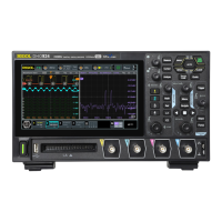
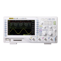
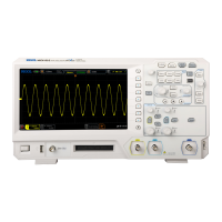
Provides physical dimensions and a front view illustration of the oscilloscope.
Guides on initial setup, including tilting, connecting power, turn-on checks, and probe connection.
Describes the main components of the oscilloscope's graphical user interface and their functions.
Instructions on how to activate or deactivate analog input channels for signal display and measurement.
Details on modifying the vertical scale (Volts/div) to adjust waveform amplitude for optimal viewing.
Explains how to set the horizontal scale (time/div) to control the time window displayed.
Describes how to use zoom mode to horizontally expand waveforms for detailed analysis.
Specifies the input signal (analog channels, AC line, EXT) to be used for triggering.
Details on setting the voltage threshold to determine the trigger point on signal edges.
Explains Auto, Normal, and Single trigger modes for capturing specific events or continuous display.
Covers setting measurement sources, enabling functions, and statistical analysis for waveform parameters.
Instructions on using cursors (X and Y) to measure specific points and values on waveforms.
Configuration for decoding parallel bus signals, including clock and data line settings.
Steps for decoding RS232 serial communication data, including source, baud rate, and data bits.
Procedures for saving setups, waveforms, or screen images to internal or external memory.
Details on how to restore the instrument to its default factory configuration settings.
Configuration of network parameters (IP, MAC, VISA) and network status prompts.
How to automatically configure settings for optimal signal display and analysis.
Instructions for performing oscilloscope self-calibration to ensure accurate measurements.
Steps for connecting and controlling the instrument remotely using a PC via USB.
Guides on connecting and controlling the instrument remotely via a local area network.
Addresses common problems like no display and unrecognized USB devices, with troubleshooting steps.
Solutions for non-responsive touch screens and issues caused by external magnetic fields.
| Channels | 2 or 4 |
|---|---|
| Input Voltage Range | ±400 V (DC + AC peak) |
| LAN Port | Yes |
| Sample Rate | 1 GSa/s |
| Trigger Modes | Edge, Pulse, Video, Slope, Runt, Pattern |
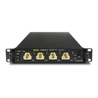
| Interfaces | USB Host, USB Device, LAN |
| FFT | Yes |
| Serial Bus Triggering and Decoding | I2C, SPI, CAN, LIN |
| Protocol Decoding | I2C, SPI, UART, CAN, LIN |
| USB Ports | USB Host, USB Device |
| Max Input Voltage | 400 V (DC + AC peak) |
| Vertical Resolution | 8-bit |
| Input Impedance | 1 MΩ ± 2% // 15 pF |