Do you have a question about the Rigol DHO800 Series and is the answer not in the manual?
Essential safety precautions for instrument operation and hazard prevention.
Explains hazard symbols and warnings used in the manual and on the product.
Guides on initial setup, including adjusting legs, connecting power, and initial checks.
Details on connecting the instrument to a power source using the provided adapter.
Essential steps for compensating the probe to ensure accurate measurements.
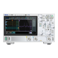
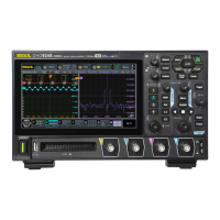
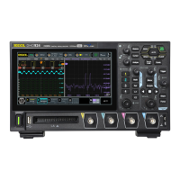
Detailed explanation of all controls, buttons, and indicators on the front panel.
Steps to turn analog input channels on or off for signal acquisition.
How to adjust the voltage per division for optimal waveform viewing.
Procedure for shifting the waveform vertically to center it or adjust its position.
Configuration of probe attenuation ratios to match the oscilloscope's settings.
Setting the time per division to control the horizontal scaling of waveforms.
Moving the waveform horizontally to align trigger points or specific events.
Expanding specific sections of the waveform for detailed analysis.
Selecting how waveform data is acquired (Normal, Average, Peak, UltraAcquire).
Adjusting the sample rate and its impact on waveform detail and aliasing.
Configuring the amount of waveform data stored per acquisition.
Selecting the signal source (channels, EXT) for triggering events.
Setting the voltage threshold for triggering waveform captures.
Choosing between Auto, Normal, and Single trigger modes.
Overview of available trigger types for capturing specific signal events.
Triggering based on the slope and level of a signal edge.
Triggering on pulses that meet specific width criteria.
Triggering based on the time duration of a signal's slope.
Triggering based on a combination of logic states (H, L, X) across channels.
Triggering when a specific pattern's duration meets criteria.
Triggering when a signal remains idle for a set duration.
Triggering on pulses that do not cross a second trigger level.
Triggering when a signal enters or exits a specified voltage window.
Triggering based on the time difference between edges of two sources.
Triggering based on setup or hold time violations in digital signals.
Triggering on the Nth occurrence of an edge after an idle period.
Performing basic math operations (A+B, A-B, A*B, A/B) on waveforms.
Performing Fast Fourier Transforms to analyze frequency spectrum of signals.
Automatically sets optimal vertical scale, timebase, and trigger for signal display.
Enabling automatic measurements of waveform parameters and displaying results.
Configuring measurement sources, enabling functions, and viewing results.
Defines and illustrates time-related measurements like Rise Time, Fall Time, Period.
Measuring voltage parameters like Vmax, Vmin, Vpp, Vamp, Vavg.
Choosing which parameters to measure and display simultaneously.
Using cursors to manually measure time and voltage values on waveforms.
Adjusting cursors manually to measure specific waveform points.
Using the built-in DVM for 4-digit voltage measurements.
Using the built-in frequency counter for period and edge event measurements.
Activating or deactivating the pass/fail test for signal compliance checks.
Defining custom masks for pass/fail criteria and saving/loading them.
Initiating and halting the pass/fail test sequence.
Decoding parallel bus signals by configuring clock and data lines.
| Channels | 2 or 4 analog channels |
|---|---|
| Vertical Resolution | 12-bit |
| Vertical Sensitivity | 1 mV/div to 10 V/div |
| Timebase Range | 1 ns/div to 1000 s/div |
| Power Supply | 100-240 VAC, 50/60 Hz |
| Waveform Capture Rate | 1, 000, 000 wfm/s |
| Interfaces | USB Host, USB Device, LAN |
| Digital Channels | Optional 16-channel MSO |
| Protocols Decoding | I2C, SPI, UART, CAN, LIN |
| Input Impedance | 1 MΩ |
| Trigger Types | Edge, Pulse, Video, Slope, Pattern, Duration, Timeout, Runt, Window |