Do you have a question about the Rigol DHO914S and is the answer not in the manual?
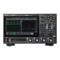
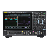
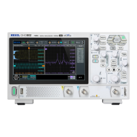
Lists key features of the DHO900 series oscilloscopes, including resolution, bandwidth, and display.
Covers inspection of packaging, instrument, and accessories upon receipt.
Outlines essential steps to get the instrument ready for operation.
Steps to activate or deactivate analog input channels for signal acquisition.
How to set the voltage per division for accurate amplitude display.
Procedure for moving the waveform vertically to position it relative to the ground level.
How to set the time per division for controlling the horizontal waveform display.
Explains different modes (Normal, Average, Peak, UltraAcquire) for waveform data acquisition.
How to select analog or digital channels as the trigger source for signal events.
Procedure for setting trigger levels (thresholds) to define signal event detection points.
Describes trigger modes (Auto, Normal, Single) for controlling acquisition behavior.
Overview of available trigger types for capturing specific signal behaviors.
How to perform addition, subtraction, multiplication, and division on waveform signals.
How to perform Fast Fourier Transform to analyze frequency spectrum of signals.
How to automatically configure settings for optimal waveform display and measurement.
Guides on setting up and performing automatic measurements of various waveform parameters.
How to use cursors for manual measurement of waveform values.
Details the 4-digit voltage measurement capabilities of the instrument.
Explains how to measure frequency, period, and edge counts of analog signals.
How to generate Sine, Square, Ramp, DC, and Noise waveforms.
Covers enabling, starting/stopping, setting sources, sweep, display, and filter for Bode plots.
How to activate or deactivate the pass/fail testing feature.
Defining the mask boundaries for pass/fail criteria and saving/loading masks.
How to initiate and halt the pass/fail testing process.
How to decode parallel bus signals by configuring clock and data line parameters.
How to decode RS232 serial communication signals.
How to decode I2C serial communication protocol signals.
How to decode SPI serial communication protocol signals.
How to decode LIN serial communication protocol signals.
How to decode CAN serial communication protocol signals.
How to search for specific edge or pulse width events in waveforms.
Procedures for saving screen images, waveforms, and instrument setups.
Performing self-calibration to ensure optimal measurement accuracy.
Performing self-tests on the instrument's keys, touch screen, screen, and modules.
Steps for connecting and controlling the instrument via USB using PC software.
Steps for connecting and controlling the instrument via LAN using PC software or web interface.
Provides solutions for common operational problems and errors encountered with the instrument.
| Channels | 4 |
|---|---|
| Vertical Resolution | 12-bit |
| Waveform Capture Rate | 1, 000, 000 wfms/s |
| Vertical Sensitivity | 1 mV/div to 10 V/div |
| Maximum Input Voltage | 400 V (DC + AC Peak) |
| USB Ports | 2 x USB Host, 1 x USB Device |
| Memory Depth | 50 Mpts |
| Display | 10.1 inch capacitive touch screen |
| Trigger Types | Edge, Pulse, Slope, Window, Runt, Pattern, Serial |
| Serial Bus Triggering and Decoding | I2C, SPI, UART, CAN, LIN |
| Input Impedance | 1 MΩ ± 1% |
| Interfaces | USB Host, USB Device, LAN |
| LAN Port | 1 |