4.3.7 Probe Compensation
When used for the first time, the oscilloscope probe must be compensated to match
the input characteristics of the oscilloscope channel to which it is connected. The
non-compensated or poorly compensated probe may cause measurement errors. The
compensation procedure is as follows:
1. Perform Step 1, 2, 3 and 4 in Function Inspection.
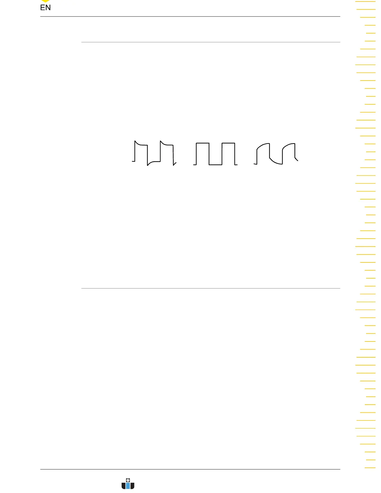
2. Check the displayed waveforms and compare them with the waveforms shown in
Figure 4.9
.
Over compensated Under compensatedPerfectly compensated
Figure 4.9 Probe Compensation
3. Use the probe compensation adjustment tool provided in the accessories to adjust
the low-frequency compensation adjustment hole on the probe until the displayed
waveform is consistent with the "Perfectly compensated" waveform shown in the
above figure.
4.4 Product Overview
Unless otherwise specified, this chapter takes DHO924S as an example to introduce
the appearance and dimensions, front and rear panels, and user interface of the
DHO900 series oscilloscope.
Quick Start
Copyright ©RIGOL TECHNOLOGIES CO., LTD. All rights reserved. DHO900 User Guide
17
www.calcert.com sales@calcert.com1.888.610.7664
0
5
10
15
20
25
30