Do you have a question about the Rigol DHO914 and is the answer not in the manual?
Provides crucial safety precautions to avoid injury and instrument damage.
Explains safety warnings and symbols used in the manual.
Defines measurement categories and their application for instrument use.
Covers initial setup steps before operating the instrument.
Describes how to connect the oscilloscope to the AC power source.
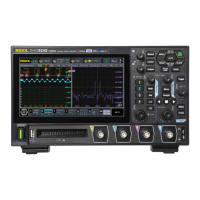
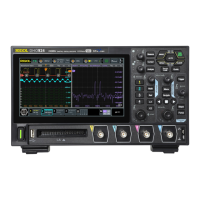
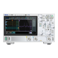
Details the components and functions of the instrument's front panel.
Illustrates and describes the connectors and ports on the rear panel.
Provides a breakdown of the main elements of the oscilloscope's user interface.
Explains how to set the volts/division for the vertical axis.
Describes how to adjust the vertical position of the waveform.
Guides on configuring probe settings, including attenuation ratio.
Details how to set an offset calibration voltage to improve accuracy.
Explains how to set the time per division for the horizontal axis.
Describes how to adjust the horizontal position of the waveform.
Explains how to use zoom mode to horizontally expand waveforms.
Explains different modes (Normal, Average, Peak, UltraAcquire) for data acquisition.
Describes the real-time sampling mode and its sample rate.
Explains the process of sampling and its impact on waveform display.
Details memory depth settings and their relation to sample rate.
Details how to select analog or digital channels as the trigger source.
Explains how to set the trigger level for analog and digital signals.
Describes the available trigger modes: Auto, Normal, and Single.
Lists and describes the various trigger types available on the oscilloscope.
Details how to trigger on rising, falling, or either edge of a signal.
Explains how to trigger based on the width of a positive or negative pulse.
Describes how to trigger based on the slope of a signal edge.
Details how to trigger based on a specific logic pattern across channels.
Explains how to trigger based on the duration of a specified pattern.
Describes how to trigger when a signal remains idle for a set time.
Explains how to trigger on pulses that cross one level but not another.
Details triggering based on high and low trigger levels.
Explains how to trigger based on the time difference between edges of two sources.
Describes triggering based on setup or hold time conditions.
Explains how to trigger on the Nth edge after a specified idle time.
Details triggering on RS232 serial communication signals.
Explains triggering on I2C serial bus communication signals.
Details triggering on SPI serial bus communication signals.
Explains triggering on CAN bus signals based on frame types or errors.
Details triggering on LIN serial bus signals.
Details how to perform Fast Fourier Transform for frequency spectrum analysis.
Explains how to perform automated measurements of waveform parameters.
Details the setup for measurement parameters and sources.
Explains how to use cursors for measuring waveform values.
Explains how to use the 4-digit digital voltmeter for voltage measurements.
Explains how to use the frequency counter for period and frequency measurements.
Introduces modulation types (AM, FM, PM) for signal generation.
Details how to define custom masks for pass/fail testing.
Details the setup and parameters for parallel bus decoding.
Explains the setup and parameters for RS232 serial decoding.
Explains the setup and parameters for I2C serial decoding.
Explains the setup and parameters for SPI serial decoding.
Explains the setup and parameters for LIN serial decoding.
Explains the setup and parameters for CAN bus decoding.
Details the self-calibration procedure for optimal measurement accuracy.
Details connecting and controlling the instrument using USB.
Explains connecting and controlling the instrument via LAN.
| Channels | 4 |
|---|---|
| Vertical Resolution | 12-bit |
| Vertical Sensitivity | 1 mV/div to 10 V/div |
| Waveform Capture Rate | 1, 000, 000 wfms/s |
| Interfaces | USB Host, USB Device, LAN, HDMI, AUX |
| FFT | Yes |
| Input Impedance | 1 MΩ ± 1% || 16 pF ± 3 pF |
| Memory Depth | 50 Mpts |
| Maximum Input Voltage | 300 Vrms |
| Display | 10.1-inch capacitive touchscreen |
| Trigger Types | Edge, Pulse, Slope, Video, Pattern, Duration, Timeout, Runt, Window |
| Operating Temperature | 0°C to 50°C |